Animation can be a nightmare if you don’t have an easy to use, well-made rig to work with, and in this tutorial Donato Marotta shows us how to create just that using joints, locators, custom attributes, set driven keys, expressions and constraints in Maya!
The tutorial is laid out as follows :
- From Step_1 to Step_6 I explain how to setup the scene before we start rigging.
- From Step_7 to Step_26 we will create all controls, joints and the parental structure.
- From Step_26 to Step_49 I will connect all joint and controls using constraints and expressions.
- From Step_50 ti Step_66 we will insert the stretch and squash control, and finally skin the bottle!
Note: Click images to access high-res versions.
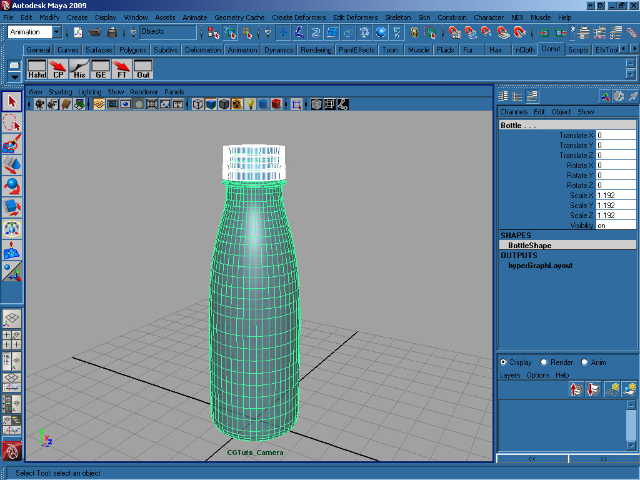
Step 1
Create a new scene and import the bottle with stopper. Select the stopper, then hold down shift and select the bottle. Press P to parent the stopper to the bottle.
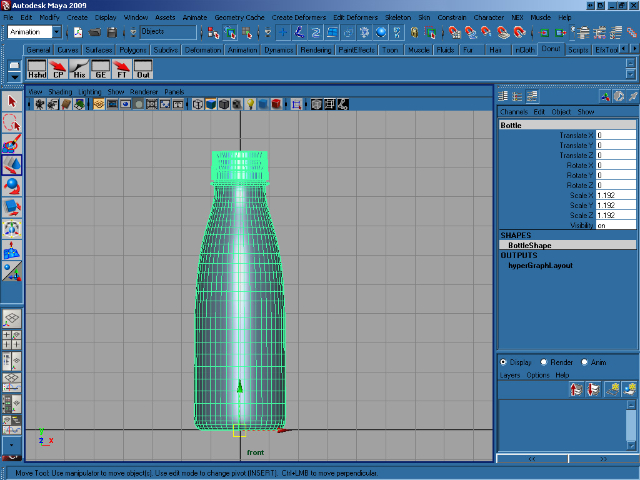
Step 2
We need to move the bottle’s pivot point, so select the bottle in the front view and press ins on your keyboard. This allows us to move the object’s pivot using the transform gizmo. Move the pivot to the bottom of the bottle and when you’re happy with it’s position, press ins again. Finally, press W and move the bottle so that it rests on Y=0 as shown.
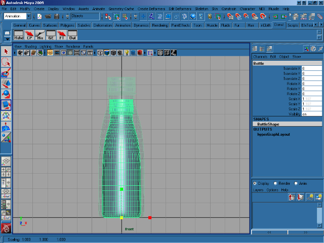
Step 3
Press R and scale the bottle proportionally so that it is eight units high, as shown.
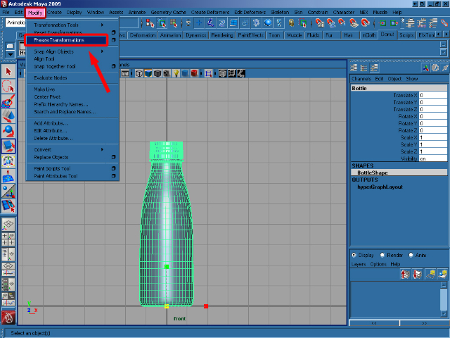
Step 4
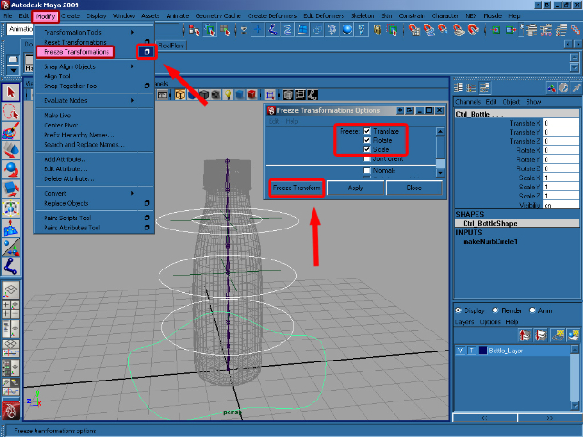
With our bottle in place, select Freeze transformations from the Modify menu.
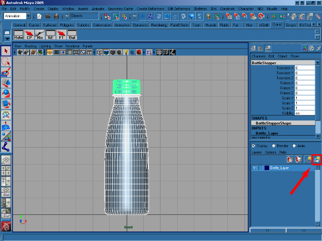
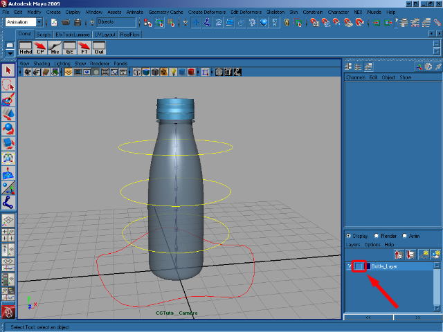
Step 5
With the bottle and stopper selected, create a new layer and rename it to Bottle_Layer. Then add the selected objects to our new layer by clicking the button shown.
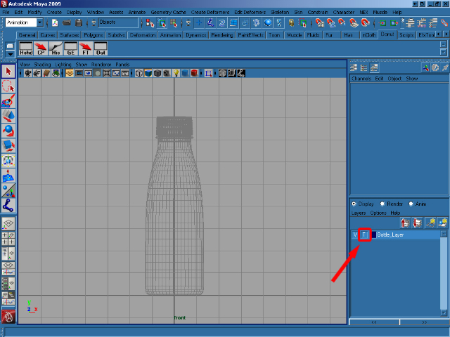
Step 6
Click on the center square on the Bottle_Layer to template the bottle, which allows us to see it, but not select it.
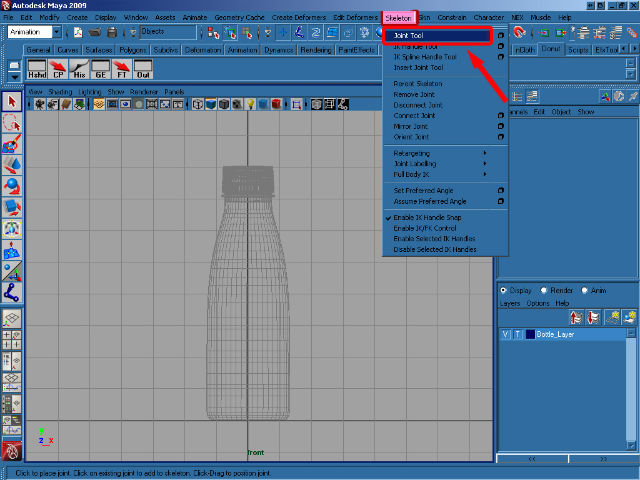
Step 7
In the Animation menu click on the Skeleton/Joint Tool.
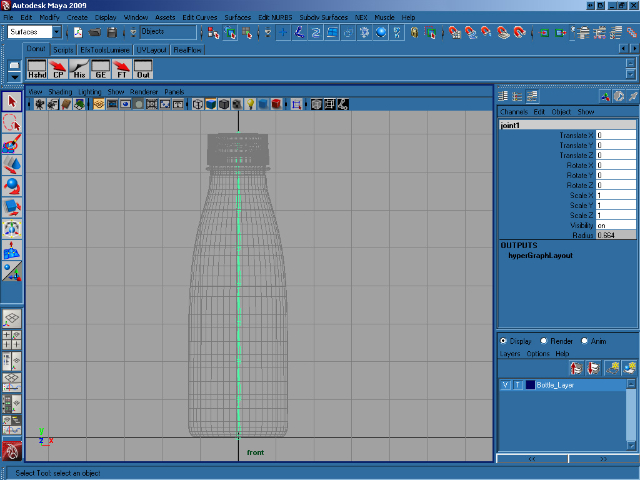
Step 8
Press hold X to enable grid snap, and create eight Joint from the bottom to the top of the bottle – one on each of our grid squares. When you’re happy, press Enter to drop the tool.
Step 9
In the Create menu select NURBS Primitives >Circle.
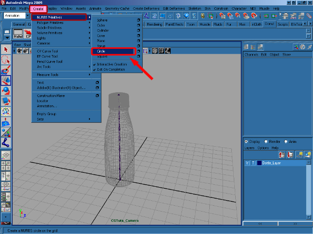
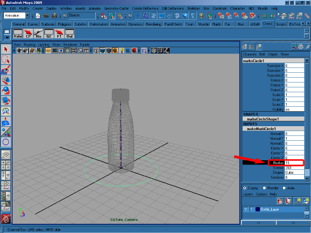
Step 10
Create a circle with a Radius of 15.
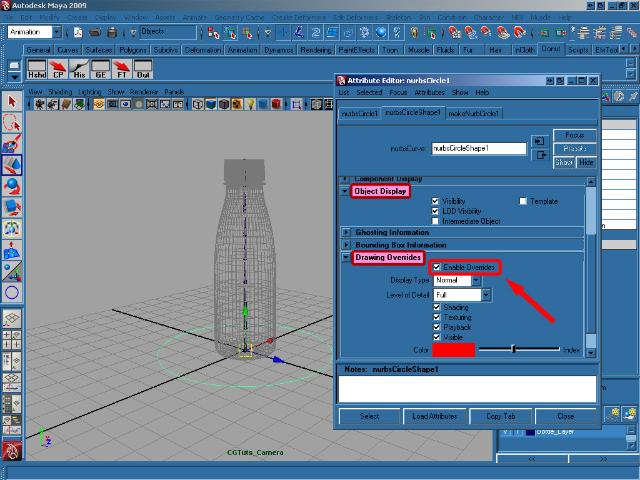
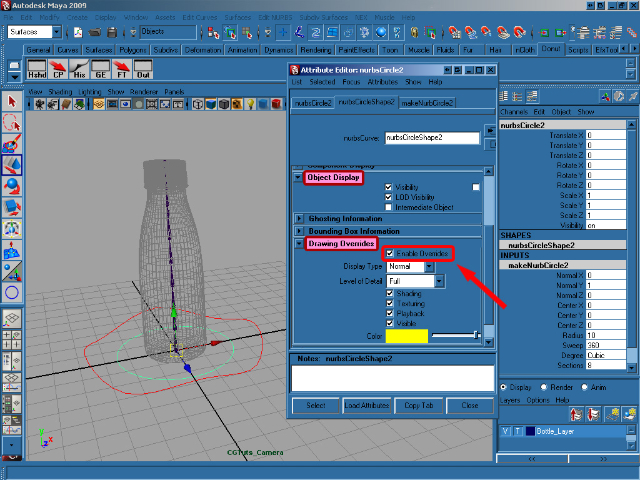
Step 11
Press Ctrl+A to activate the Attribute Editor for the object, and then go to Object Display > Drawing Overrides > Enable Overrides and choose the Red color.
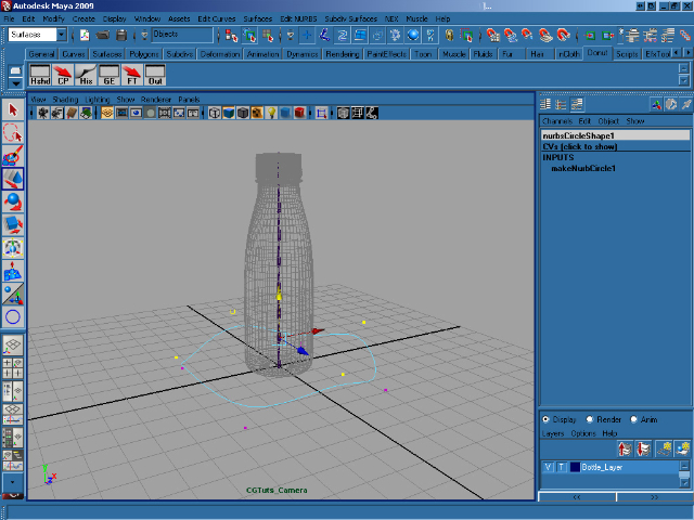
Step 12
Now we’re going to modify the circle a little bit! Right click on it and select Control Vertex. Now grab the vertices one by one and move them into place (you can create any shape you want!) When you’re done, rename the circle as Ctrl_Bottle.
Step 13
Now create another nurbs circle in the center of axis, with a Radius of 10. Then go to the Attribute Editor and make it yellow.
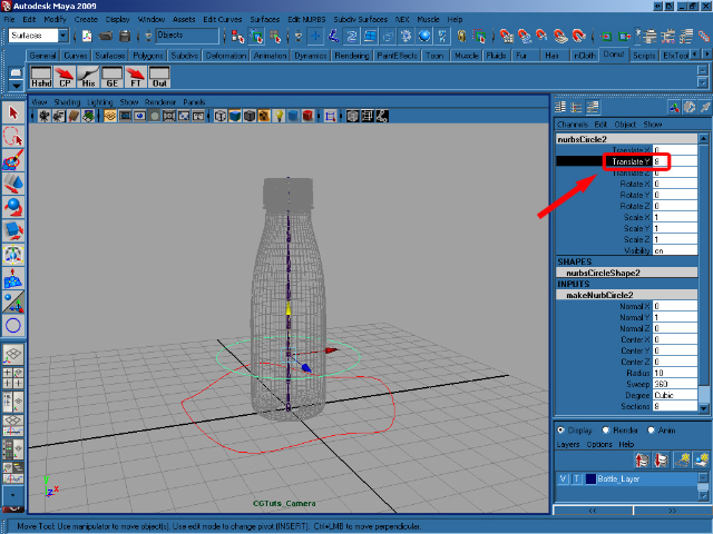
Step 14
Move the last created circle to 8 on the Y axis, and rename it as Ctrl_Spine1.
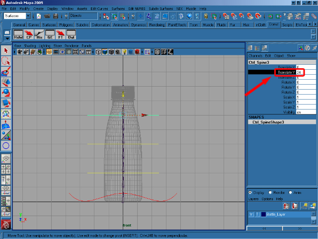
Step 15
Duplicate Ctrl_Spine1 twice, and move the first to 16 and the second to 24 on the Y axis.
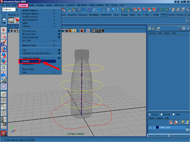
Step 16
Select menu Create > Locator.
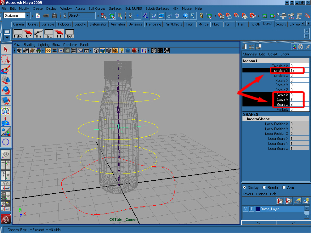
Step 17
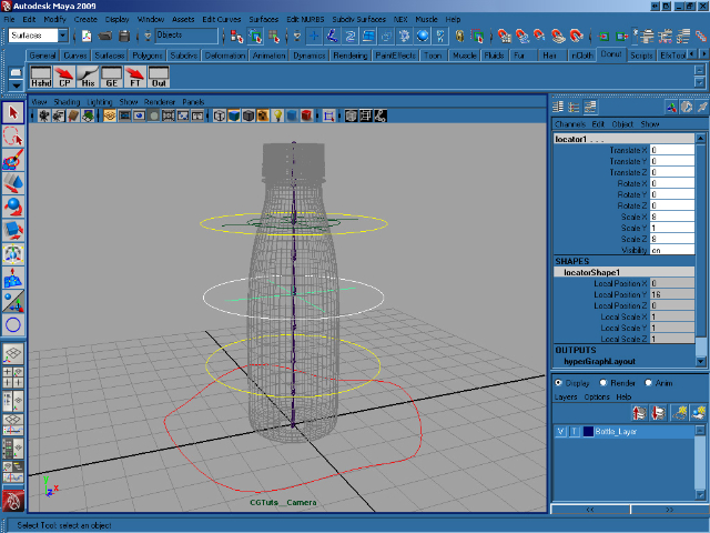
Scale the new locator proportionally to 8, move it to 16 on the Y axis and rename it to locator1.
Step 18
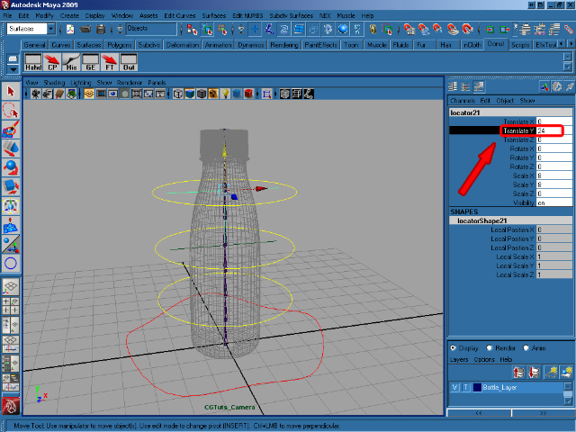
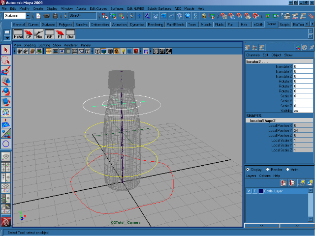
Duplicate the locator, and move the duplicate to 24 on the Y axis, to match the position of the circle. Rename it to locator2.
Step 19
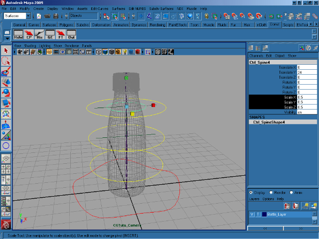
Now select Ctrl_Spine3, duplicate it, and scale it proportionally to 0.5.
Step 20
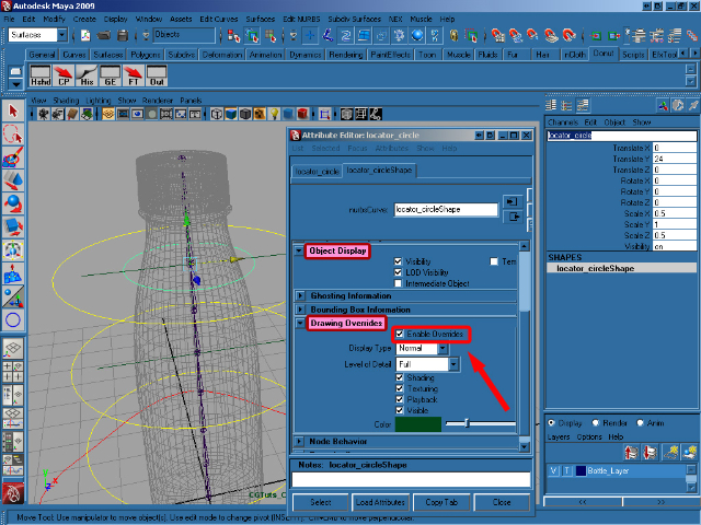
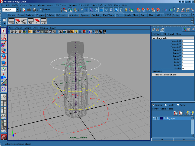
Color the last duplicated Circle to match the color of it’s locator and rename it to locator_circle.
Step 21
Now select all of the created controls except locator1 and locator2, and go to Modify > Freeze Transformation (Options). In the options, select Translate Rotate Scale and then click on Freeze Transform.
Step 22
Select Ctrl_Spine3, and holding down Shift select locator_circle. Now press P to parent them together.
Step 23
Select locator_circle, and again holding down shift select locator2. Press P to parent them together.
Step 24
More parenting! Select Ctrl_Spine2, hold shift and select locator1 and then press P to parent.
Step 25
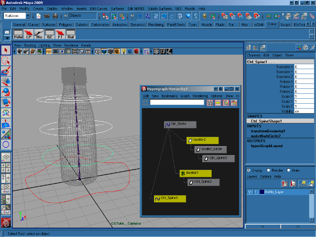
Now select locator2, hold shift and select locator1, Ctrl_Spine1 and Ctrl_Bottle. With all 4 selected, press P to parent. If you open the Hypergraph, it should look very similar to the image below.
Step 26
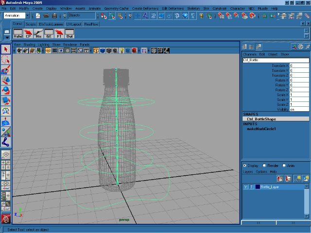
Now with our controls in place and set-up, we’ll start work on the joints. Select joint1, hold shift and select Ctrl_Bottle and press P to parent all of the joints to the main control, Ctrl_Bottle.
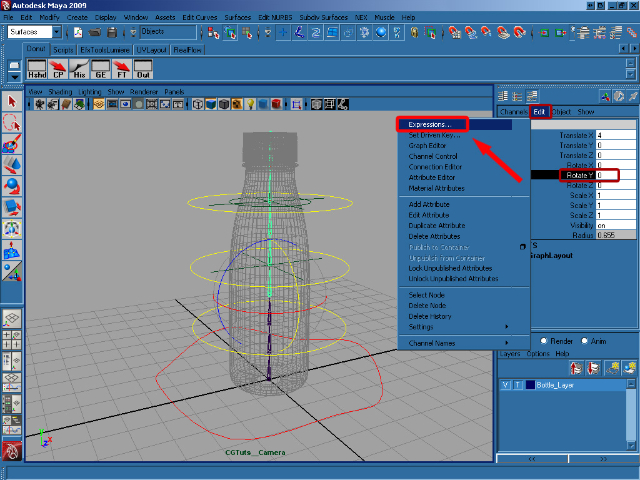
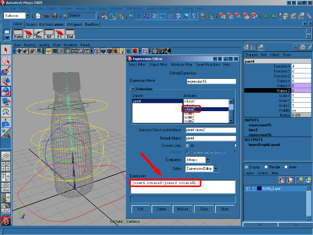
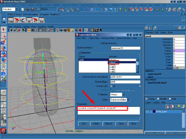
Step 27
Select Joint4 and in the Channel Box select Rotate Y and at the top of the Channel Box go to Edit > Expressions to open the Expression Editor.
Step 28
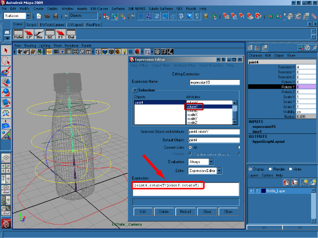
Add the following expression to rotateY and then click on Create :
joint4.rotateY=joint3.rotateY;
Step 29
Now select rotateZ in the Expression Editor and add/create this expression :
joint4.rotateZ=joint3.rotateZ;
Step 30
Select joint2, and then select rotateY in the Expression Editor. Add/create this expression :
joint2.rotateY=Ctrl_Spine1.rotateX/4;
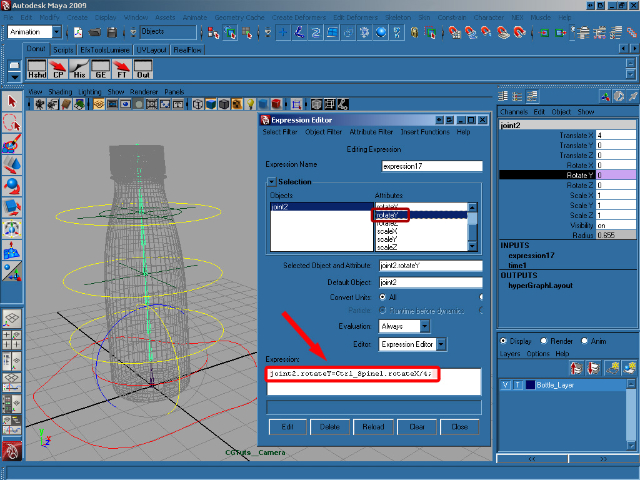
Step 31
Select rotateZ and add/create this expression :
joint2.rotateZ=-Ctrl_Spine1.rotateZ/4;

Step 32
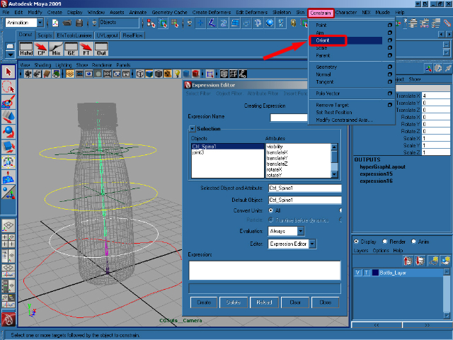
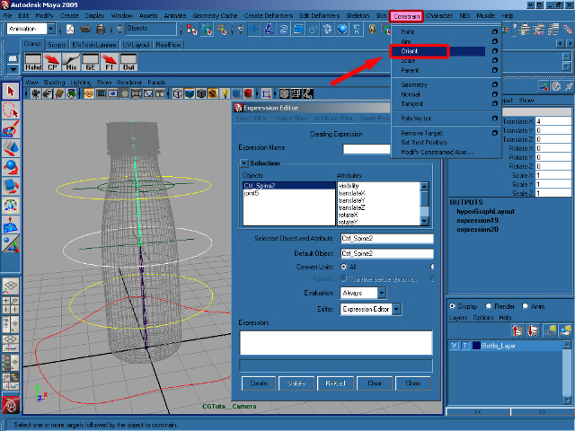
Select Ctrl_Spine1 and shift select joint3. In the Animation menu select Constrain/Orient.
Step 33
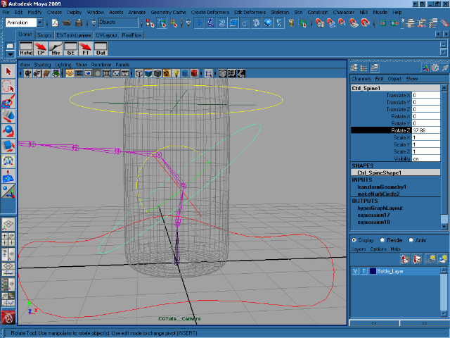
As you can see to the image below, rotating Ctrl_Spine1 correctly rotates the joints. Now it’s time to repeat the process for the other controls.
Step 34
Select joint6 and then select Rotate Y in the Channel Box, open up the Expression Editor as before, and add this expression to rotateY, remembering to hit Create when you’re done :
joint6.rotateY=joint5.rotateY;
Step 35
Select rotateZ in the Expression Editor and add/create this expression :
joint6.rotateZ=joint5.rotateZ;

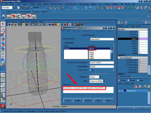
Step 36
Select locator1 and then in the Expression Editor select rotateX and add/create this expression :
locator1.rotateX=Ctrl_Spine1.rotateX*3;
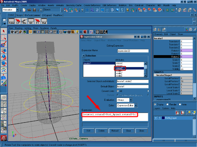
Step 37
Select rotateZ and add/create this expression :
locator1.rotateZ=Ctrl_Spine1.rotateZ*3;
Step 38
Select Ctrl_Spine2, shift select joint5 and select Constrain/Orient from the Animation menu.
Step 39
Select joint5, shift select locator1 and choose Constrain/Point (Options) from the same menu.
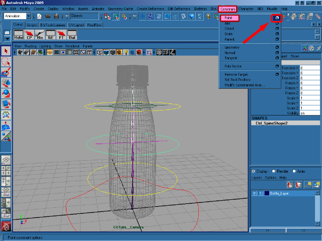
Step 40
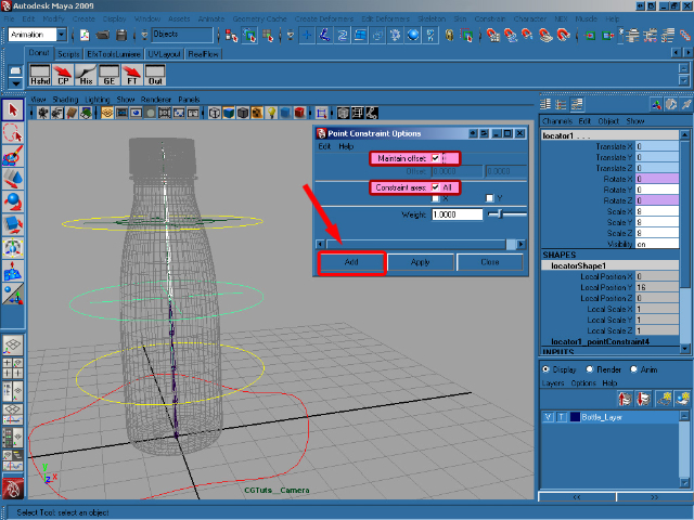
In the Point Constraint Options, select Maintain offset and Constraint axes (All) and click on Add.
Step 41
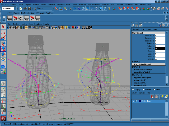
As you can see in the image below, we can now rotate Ctrl_Spine1 and Ctrl_Spine2 separately, although the second is influenced by the first.
Step 42
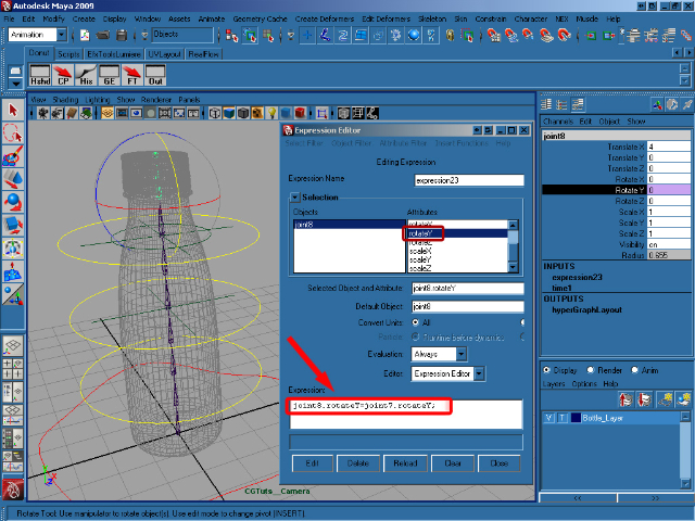
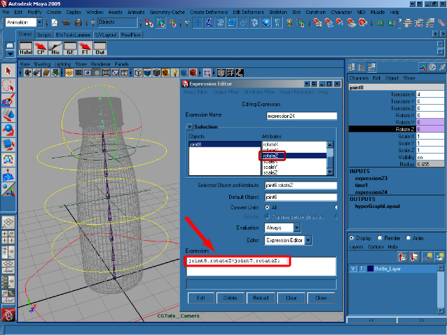
Now select joint8, bring up the Expression Editor, select rotateY and add/create this expression :
joint8.rotateY=joint7.rotateY;
Step 43
Select rotateZ and add/create this expression :
joint8.rotateZ=joint7.rotateZ;
Step 44
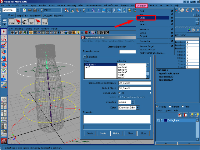
Select Ctrl_Spine3, shift select joint7 and select Constrain/Orient from the animation menu.
Step 45
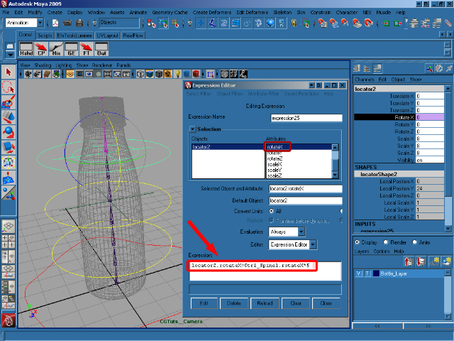
Select locator2, open the Expression Editor, select rotateX and add this expression :
locator2.rotateX=Ctrl_Spine1.rotateX*5;
Step 46
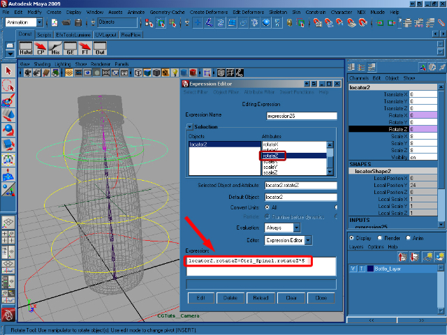
Select locator2, then rotateZ in the Expression Editor and add/create this expression :
locator2.rotateZ=Ctrl_Spine1.rotateZ*5;
Step 47
Select locator_circle, and add this expression to rotate X :
locator_circle.rotateX=Ctrl_Spine2.rotateX*3;
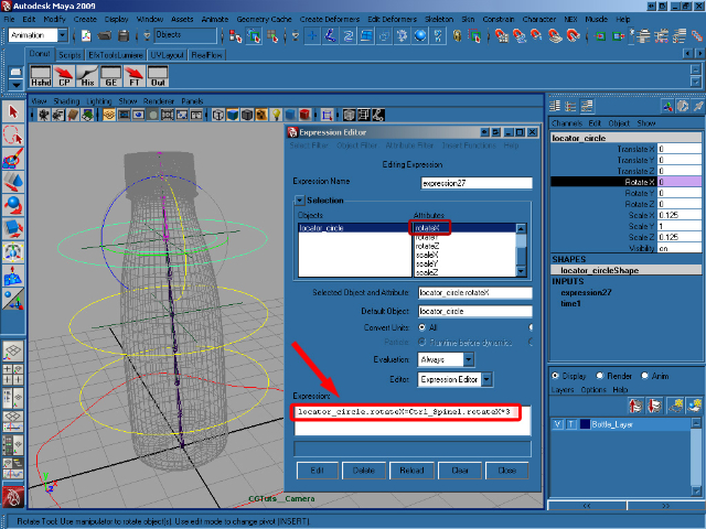
Step 48
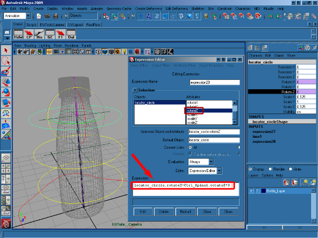
Select rotateZ and add this expression :
locator_circle.rotateZ=Ctrl_Spine2.rotateZ*3;
Step 49
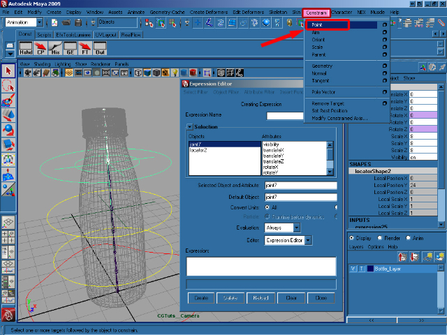
Select joint7, shift select locator2 and select Constrain/Point from the Animation menu.
Step 50
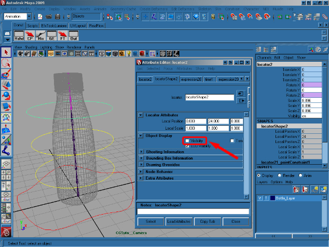
Select locator1 and open the Attribute Editor (Ctrl + A). In the Object Display Panel turn off the Visibility. Now do the same thing for locator2 and the circle_locator.
Step 51
In the Layer Editor, click twice on the middle box on our BottleLayer make the bottle selectable.
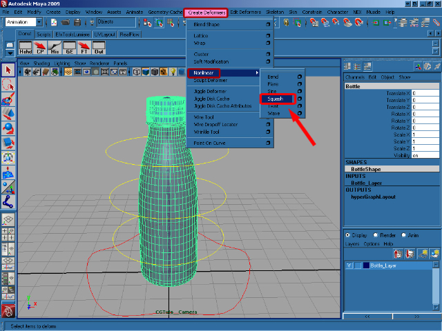
Step 52
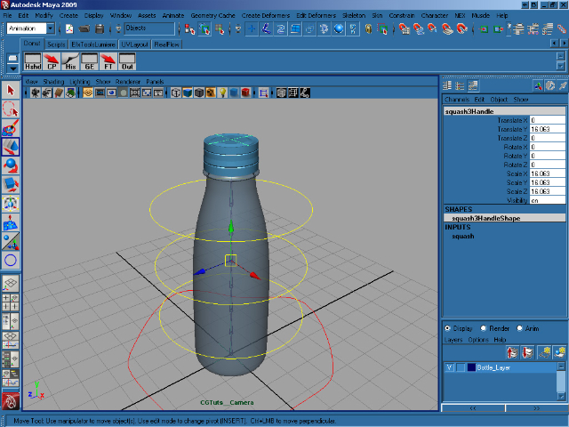
Select the bottle and, making sure you’re viewing the Animation menus, go to Create Deformers > Nonlinear > Squash.
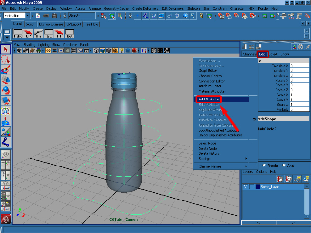
Step 53
Select Ctrl_Bottle and in the Channel Box click on Edit > Add Attribute.
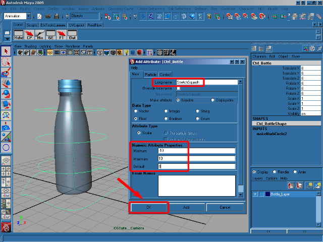
Step 54
In the Add Attribute dialog, for Long name write Stretch Squash, in Data Type choose Float, in Numeric Attribute Properties insert a Minimum of -10 and a Maximum of 10, and finally add a Default of 0. Click on OK to add our new attribute.
Step 55
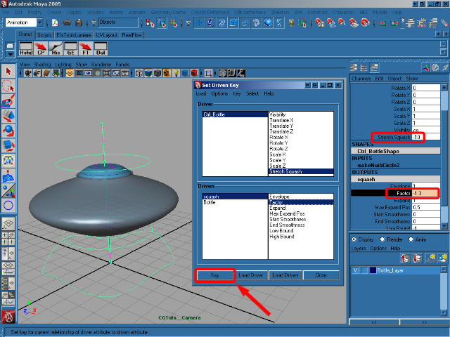
Now we have our new attribute, we need to make it do something! In the Channel Box select Stretch Squash and go to Edit > Set Driven Key.
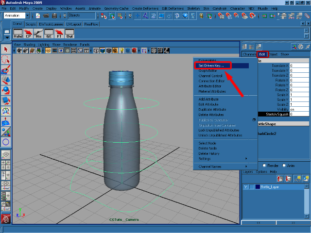
Step 56
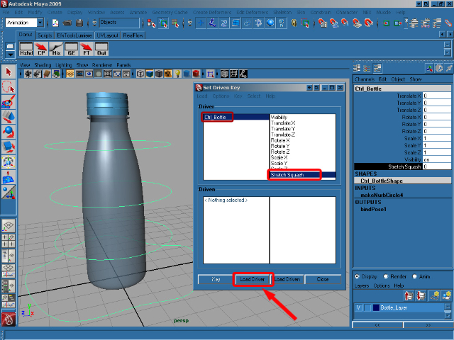
Select the Ctrl_Bottle and in the Channel Box click on our new Stretch Squash attribute. In the Set Driven Key window click Load Driver to add our Ctrl_Bottle in as our driving object. In the now-populated Driver box select Ctrl_Bottle and then Stretch Squash.
Step 57
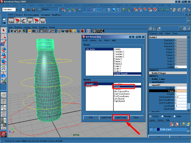
Now we need to choose the driven object. So select the Bottle and in the Channel Box select squash in the INPUTS section. Now click Load Driven in the Set Driven Key window to populate the driven section. Click on squash in the Driven Box and then select Factor. With our driver and driven attributes setup, we can now click Key to create our first connection.
Step 58
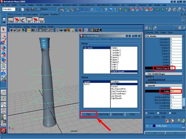
Now select Ctrl_Bottle and set the Stretch Squash attribute to 10. Select squash in the OUTPUTS section of the Channel Box and change the Factor value to 0.7. Back in the Set Driven Key window, click on Key to create another connection.
Step 59
Set the Ctrl_Bottle‘s Stretch Squash attribute to -10, select squash in the OUTPUTS section and change the Factor value to -1.3. Now create our final key by clicking Key in the Set Driven Key window.
Step 60
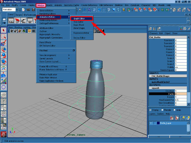
Set the Stretch Squash attribute back to 0 and close the Set Driven Key window. Go to Window > Animation Editor > Graph Editor.
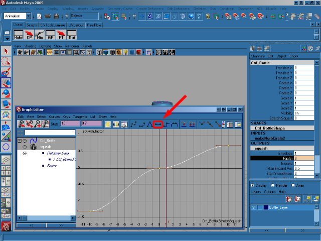
Step 61
Select squash in the OUTPUTS section of Ctrl_Bottle to update the Graph Editor. Select all of the animation keys and press F to smooth them as you can see in the below image.
Step 62
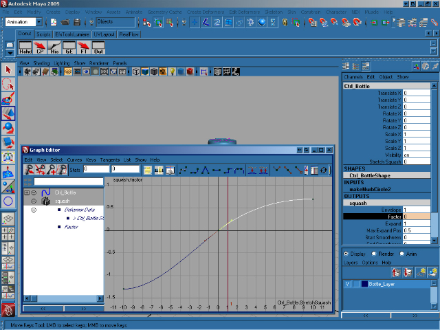
With that done, now select just the middle key in the Graph Editor and, using the bezier handles sticking out of the key itself, adjust the animation curve to smooth things out fully as you can see below. Close the Graph Editor.
Step 63
Select the squashHandle and press Ctrl + H to hide it.
Step 64
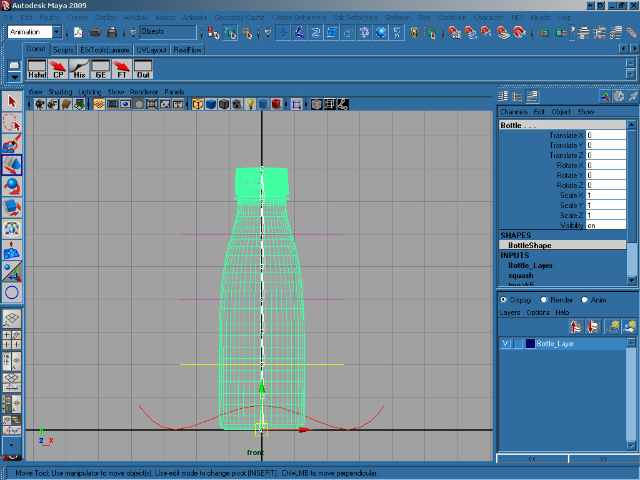
With our rig in place, and our squash/stretch complete, we now need to connect the rig up to the bottle geometry itself. Go to the front view and press 4 to switch to wireframe view. Select joint1 and Shift select the bottle.
Step 65
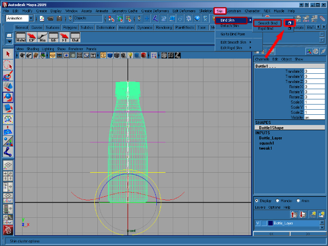
In the Animation menu click on Skin > Bind Skin > Smooth Bind (options).</p
Step 66
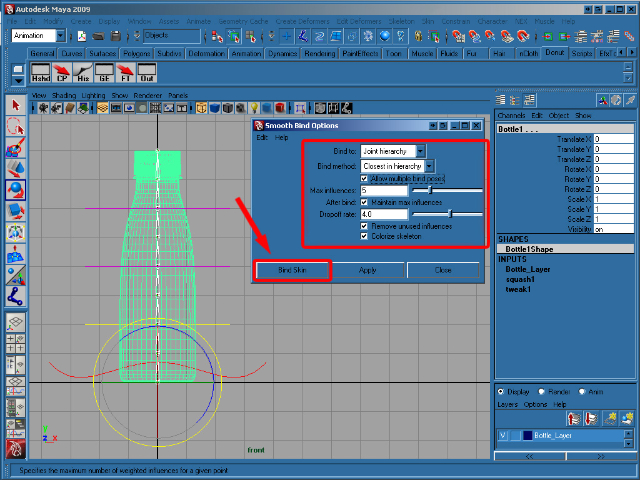
In the Smooth Bind Options windows set Bind to to Joint hierarchy, Max influences to 5, and then click on Bind Skin. Finally select Ctrl_Spine1, in the Channel Box, right-click Rotate Y select Lock Selected to disable editing for this channel, as it will be affected by our rig. Now repeat this lock for Ctrl_Spine2 and Ctrl_Spine3.
And that’s it, you’re ready to animate! Play around with the rig and see what you can come up with! I hope you enjoyed the tutorial, and if you have any questions just let me know in the comments.
Don’t miss more CG tutorials and guides, published daily – subscribe to Cgtuts+ by RSS.