With the release of Illustrator CS5, Adobe introduces the new Perspective Drawing tool set, which allows you to create images in accurate 1-, 2- or 3-point perspective. Perspective Drawing alleviates tedious measuring and scaling, letting you concentrate on artistry, not arithmetic. In this tutorial, you’ll learn how to set up a Perspective Grid and use the Perspective tools to draw and modify shapes. You’ll learn how to use and edit Symbols and live text, all in perspective. We’ll also review best practices for perspective drawing.
The perspective drawing feature takes a lot of getting used to. I must admit that the first time I laid hands on it, I felt like I did the very first time I used Illustrator — I thought I knew what it was supposed to do, but had no idea how to make it work. But once you play around with it for a while, and start to think in perspective, it will become less intimidating. This is an advanced tutorial and assumes a high level of Illustrator experience. Let’s get started!
Getting to Know the Tools
There are three main components of the Perspective Drawing feature: The Tools, the Grid and the Widget. The Perspective Grid Tool (Shift + P) is used for working solely with the grid itself — moving it, changing its size, and adjusting its settings. The Perspective Selection Tool (Shift + V) is used for selecting and modifying objects while in perspective. Both are part of the Drawing set in the Tools panel, and are located below the Free Transform tool. I like to tear off the tools for easy access, and to remind me to use them.
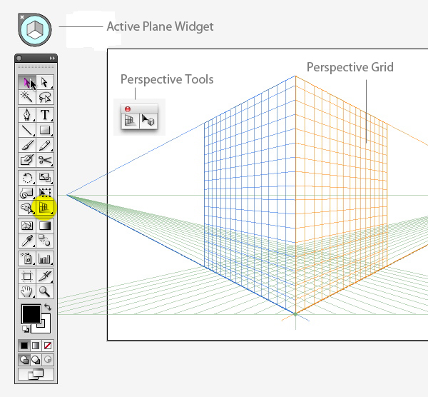
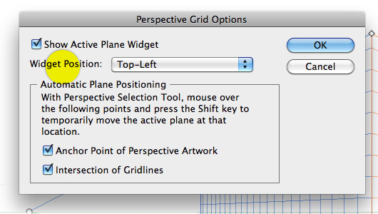
When you click the Perspective Tool, two things appear in your workspace: The Perspective Grid and the Active Plane Widget. You can change the placement of the Widget by double-clicking on the Perspective Grid tool to bring up its options. The Widget can only be placed in one of the four corners — you can’t move it freely.
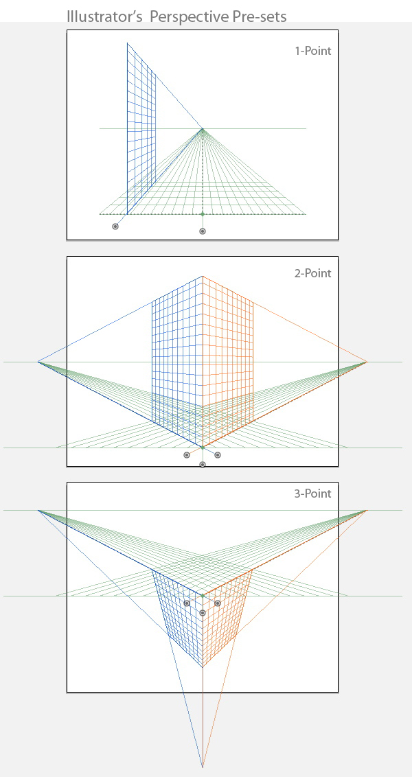
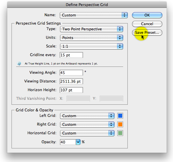
CS5 comes with three standard perspective grids. To view each and switch between them, go to View > Perspective Grid. The "1P," "2P" and "3P_Normal View" are the presets. Once you start modifying and creating your own grids, you can save those as presets by going to Define Grid under the View menu. Here you can also adjust some unit and color preferences.
Getting to Know the Grid
When working with perspective drawing, it’s important to set up the grid accurately at the outset. You will do all the grid set-up with the Perspective Grid Tool (Shift + P) — that is its sole function, and the grid controls will only be visible when this tool is selected.
There are several controls on the grid which allow you to modify it. Here’s an overview: (Tip: I find it helpful to hide the Artboard when working with perspective. There are a lot of lines on the screen already, and the Artboard edges seem to get in the way)
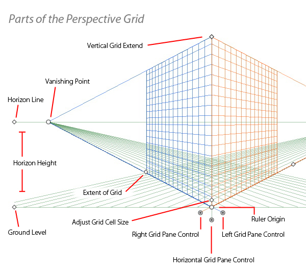
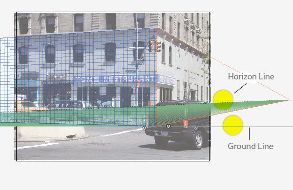
Each grid has a Ground Line, which can be thought of as the actual ground on which an object is resting. When you move the Ground Line by dragging its diamond-shaped handle, the entire grid moves. The Horizon Line corresponds to the viewer’s eye level. If you drag the Horizon Line down closer to the Ground Line, it is as if the viewer is small (relative to the overall composition), and looking up at an object on the grid. Drag the Horizon Line up away from the ground, and you can imagine being above an object looking down on it.
On a 2-point perspective grid, there are both left and right Vanishing Points. These are the points on the horizon at which parallel lines converge. In other words, where the image recedes so far in the distance it appears to vanish. These points slide left and right, and determine the severity of the perspective.
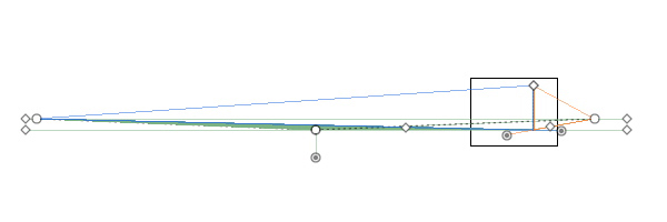
If you lock the Station Point (View > Perspective > Lock Station Point) then move one of the Vanishing Points, the two planes move together, and appear to rotate around the center point.
The diamond just above the Station Point is used to adjust the cell size, or how many grid lines are on each plane. Move it up or down according to your preference.
The left and right Grid Pane Controls are used to move their respective planes. The Left Grid Plane control is on the right — moving it is like opening a gate whose "hinge" is the vanishing point. Same with the right side; its control is to the left.
After you’ve played around a bit with the grid, you can re-set it to the normal 2-point perspective.
Part I – Setting up the Grid
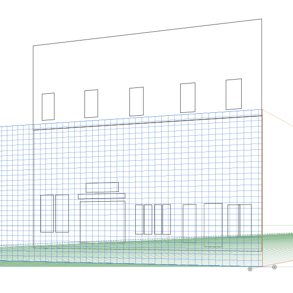
Of course, you can use one of the pre-sets and just start drawing, but for the purposes of this tutorial, we’ll use a photographic reference and set up a custom grid. Note that any photo or drawing you use will likely not match up with the grid exactly. Camera lenses distort, and it is nearly impossible to draw — without measurement tools — in mathematically-precise perspective.
Step 1
Place your photo or drawing on its own layer, and make that layer a Template (Plus members may download the source file for this tutorial, with the photo already embedded). Make the grid visible by clicking on the Perspective Grid tool. Using the Perspective Grid tool, move the Ground line (and thus the entire grid) to about the bottom of the sidewalk in the photo. Move the Horizon line accordingly, to about eye level.
Step 2
Position the top center of the grid at the top of the first floor of the building, at the corner. This will line up the two grid planes with the edge of the building.
Step 3
Drag out the left vanishing point so that the grid lines match the angles of the building. You’ll probably have to zoom way out in order to drag the point far enough. In the image below, you can see how far you’ll need to zoom out, relative to the art board.
Do the same with the left grid plane. Once you’re confident the grid matches, you may wish to lock it (View > Perspective Grid > Lock Grid).
Part II — Drawing in Perspective
Now we’re ready to draw. There are two groups of tools that work with perspective drawing, Line Tools (Line Segment, Arc, Spiral, Rectangular Grid, Polar Grid) and Shape Tools (Rectangle, Rounded Rectangle, Ellipse, Polygon, Star {but not the Flare tool}).
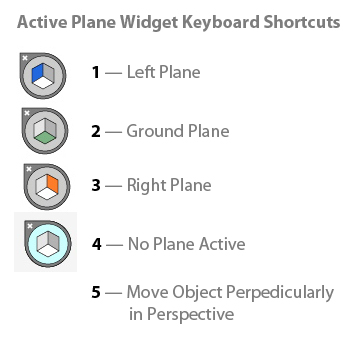
Where you draw is determined by the Active Plane Widget. It is a good idea to become familiar with the keyboard shortcuts used for the Widget. They are simply the numbers 1 through 5 on the keypad. They will speed up your workflow, and there are some instances in which there is no menu alternative.
Step 1
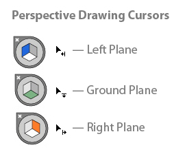
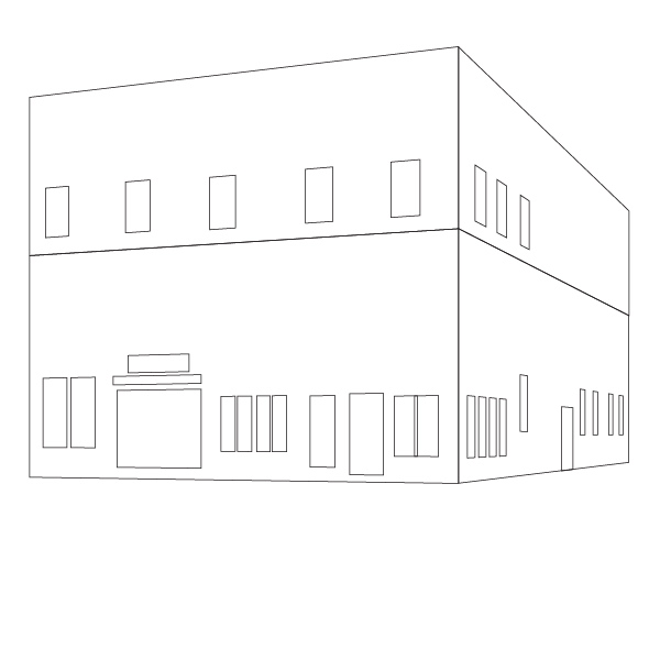
Create a new Layer above the Template layer and name it "Building Front". Choose the Perspective Selection tool (Shift + V) and click the left (blue) plane on the Widget. This activates the left plane. Now select the Rectangle tool (M) and begin to draw. You will notice immediately that the rectangle conforms to the plane. You’ll also notice that the cursor crosshairs now has a left-facing arrow next to it. This is a visual cue that lets you know which plane is active as you draw.
Switch back to the Perspective Selection tool and move your rectangle. Observe how it changes in space. Note that even if you move the object beyond the bounds of the visible grid, it will still be in perspective. Another visual cue when working in perspective is the appearance of the corner handles on an object’s bounding box. When an object is attached to a plane, the handles are solid, rather than hollow as they are for normal drawing.
Begin roughing out the drawing, creating the face of the building and doors and windows. Stick with basic rectangles for now — we’ll get to the curved windows in a minute. To scale or move an object, use the Perspective Selection tool (Shift + V). If you hold down the Option/Alt key and drag a rectangle, the resulting copy will be in perspective.
Your drawing should look something like the image below:
Step 2
Create a new layer for the side of the building. As before, rough out the structure of the right side of the building and its windows.
Step 3
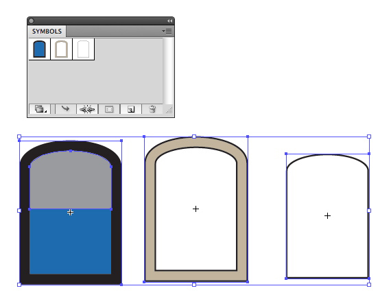
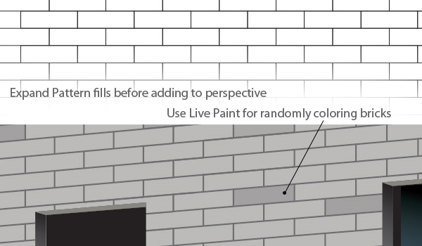
For rounded objects, it’s sometimes better to create them straight on, then bring them into perspective. You’ll do this for the arched windows. For objects that you’ll use more than once, it’s a good idea to make them into Symbols. That way you’ll have a library of objects you can go back to when you need one. This is not to be confused with mapping art in 3-D, it’s just a way to keep "flat" copies of certain objects handy. Because once an object is moved into perspective, it can’t be reverted back to its original state. Another reason for using Symbols is that you can double-click on one to edit its appearance. Edit one symbol, and all instances of that symbol will be updated.
Since this is an advanced tut, I’m going to assume that you know how to make the window shapes. You can make a basic shape and/or ones with a little more embellishment. Drag each one into the Symbols panel.
Step 4
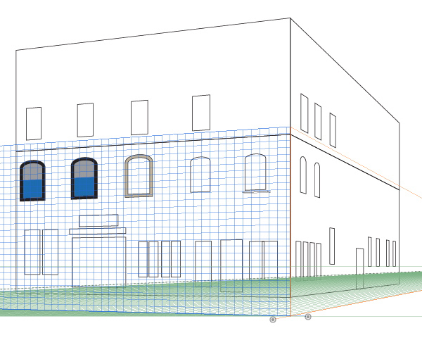
Drag out a window symbol to the art board. Make sure the Left Pane is active, and using the Perspective Selection tool, drag the window into place. You’ll see that it snaps to perspective. Add more arched windows to the left and right planes. Your drawing should look something like the image below:
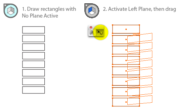
Step 5
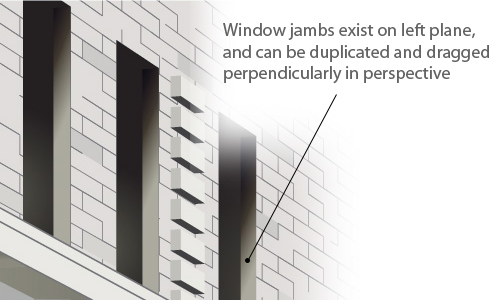
Just as you can drag Symbols into perspective, you can do the same with regular flat objects. For the columns of protruding bricks, first click the "no plane" section of the Active Plane Widget. Now draw a series of rectangles and group them. Then press 1 or click the Left Plane on the Widget and drag the group. It will snap to perspective. Option-drag to position another group at the edge of the building.
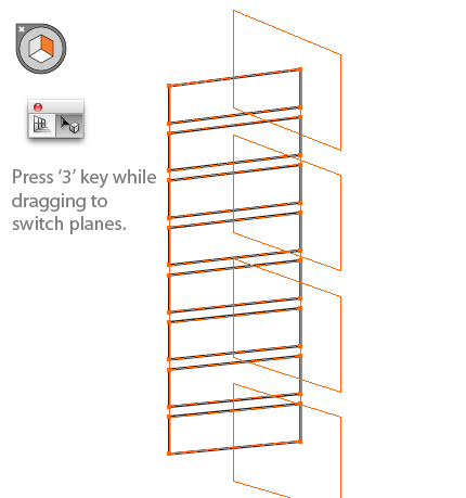
Step 6
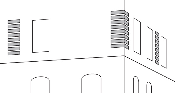
To place this group onto the right plane, make a copy of it, then as you drag, press the 3 key to switch to the right plane. The placed groups (highlighted in gray) should look like the image below:
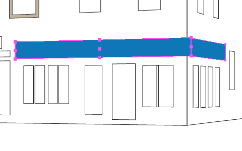
Step 7
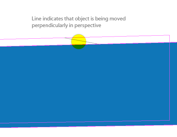
Make a new layer for the sign. Activate the left plane and draw out a rectangle. The sign has some dimension and doesn’t lay flat against the wall, so you can pull it away from the wall (towards the viewer) but keep it in perspective. Select the shape with the Perspective Selection tool, hold down the ’5′ key and drag it up a bit. A line indicates that you are dragging perpendicularly, in perspective. Do the same on the right, lining up the right rectangle with the left one.
Step 8
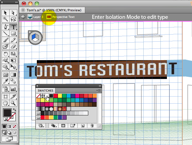
To add text to the sign, type with the Type tool. It will be normal, non-perspective type, but once you switch to the Perspective Selection tool, activate a plane and drag, the text will snap into perspective. Move and scale it as necessary. It will look as though the type is outlined, but it remains fully editable.
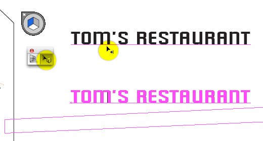
To edit type in perspective, double-click on it to enter Isolation Mode. Change the color, font or type new text, then press the Escape key twice to return to perspective. (Note: Due to font licensing restrictions, the type in the sample file has been expanded and is no longer editable)
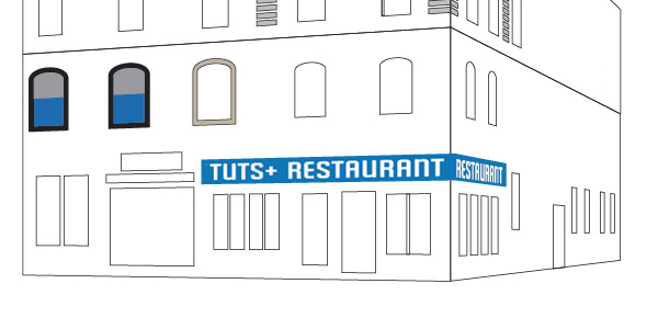
Place type on the right side of the sign. Your illustration should look like the image below
Part III — The Details
With the structure of the illustration in place, the rest is all details. This is no small task — it will take more than a few fills and strokes to fully round out the illustration. You will need to bring all of your Illustrator skills to bear to take a mathematically-sterile perspective drawing and bring it to life.
Most of these details will be added in perspective. Here are some examples:
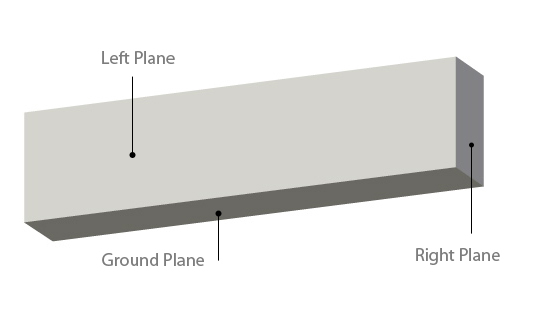
The block below is made of three separate rectangles, each on its own perspective plane.
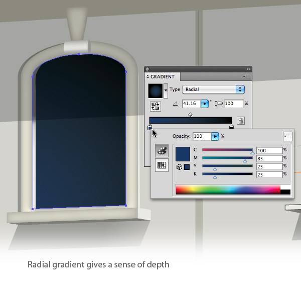
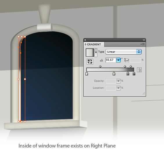
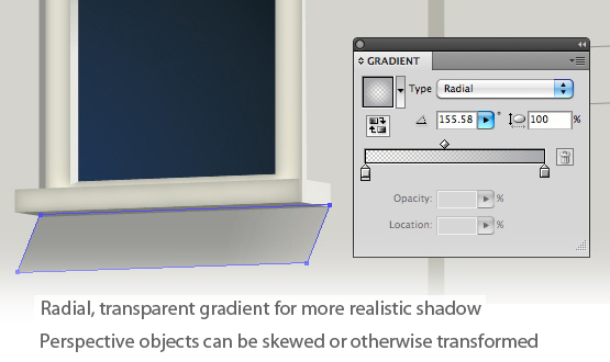
Judicious use of gradients will add depth and richness to your illustration, and careful positioning of objects will lend realism:
Best practices
-
Learn and use the keyboard shortcuts.
Keyboard shortcuts rock in any application, but for the perspective Drawing, they’re essential. You’ll be tempted to press ‘V’ every time you want to move something, but it won’t take long to remember to press Shift-V. And the Active Plane shortcuts — 1, 2, 3, 4, 5 — what could be easier? - Use Smart Guides.
Crucial for lining up objects and making your drawings perfect. - Use Symbols.
Think of the Symbols panel as a library. It can store objects in their flat, non-perspective state. You’ll be glad to have it. - Define and save your own grids.
Go to View > Perspective Grid > Define Grid. When you’ve gone to the trouble to set up a custom grid, save it. That way if you ever want to make another illustration built on that grid, you’ll have it handy. And should you experience a crash or otherwise lose the drawing you’re working on, you can start over using the saved grid.
Conclusion
Just when you think Adobe couldn’t possibly add something new to Illustrator, it does. And you wonder how you ever got along without it. It was always possible to make perspective drawings with Illustrator, if you had the time and patience. Now with CS5, you can let Illustrator do the tedious work, while you concentrate on the fun part. Download a free trial of CS5 at Adobe.