Water pipes and taps are known for more than two thousand years. The first water pipes were built in ancient Rome and named aqueducts. Let’s illustrate now this symbol of irresistible flight of engineering ideas and of mankind’a progress. While reading this tutorial, you’ll undoubtedly learn excellent vector illustration techniques, and use various powerful Illustrator tools. We’ll construct a water tap object using gradient meshes, art brushes, and more. Follow along, while creating your own vector artwork.
Step 1
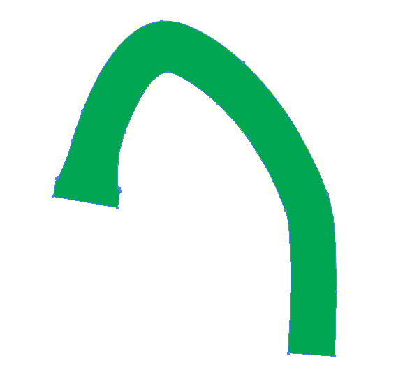
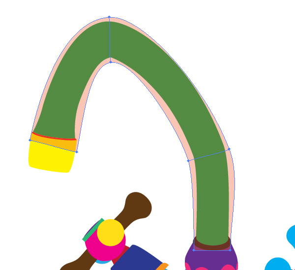
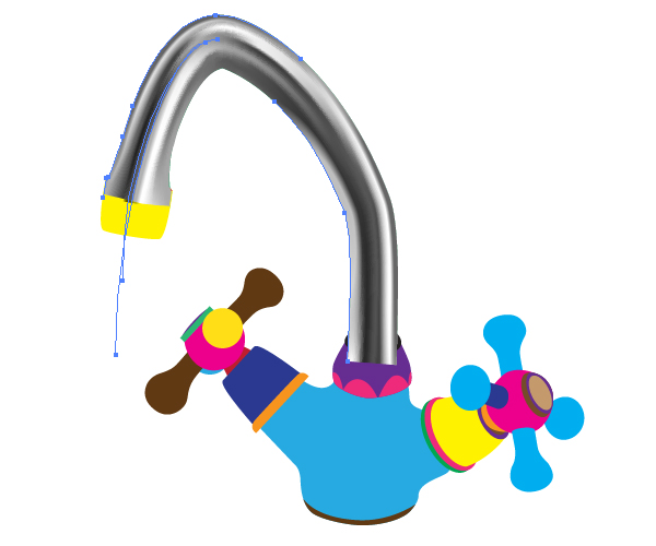
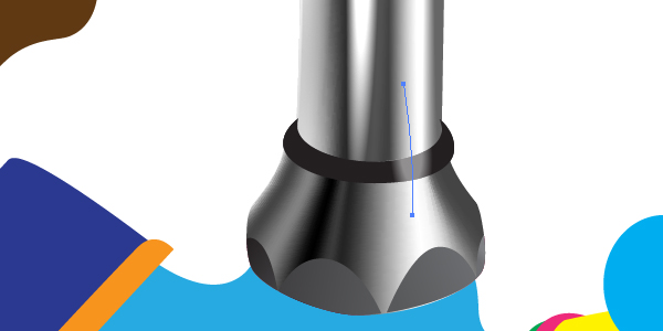
First of all, you need to create the main geometry. You must achieve the following picture shown below.
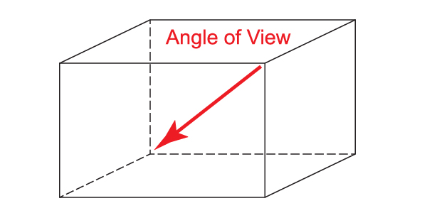
If you know how to achieve this, do it by yourself without assistance and go immediately to Step 12. Otherwise you should read carefully the beginning steps of this tutorial. Let’s define the angle of view of the tap in our illustration’s space.
Step 2
Take the Pen Tool (P) and illustrate a path which will represent the main tube of the tap.
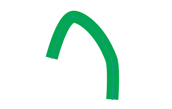
Go to Object > Expand. Then go to Object > Ungroup. Change the path slightly to the following form by using the Direct Selection Tool (A).
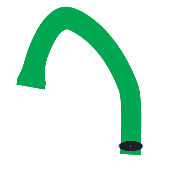
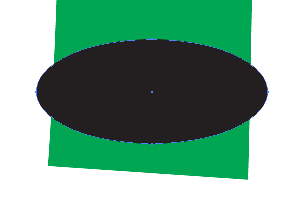
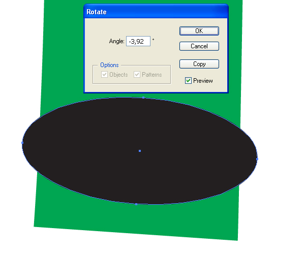
Step 3
Take the Ellipse Tool (L) and picture an elliptical path in the lower part of the main green tube, as shown in the diagrams below.
Rotate it slightly by going to Object > Transform > Rotate, or by using the Rotate Tool (R).
Step 4
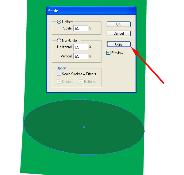
Change the opacity of the ellipse in order to have the possibility to watch the underlying green path.
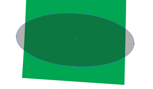
Go to Object > Transform > Scale and decrease the value of scaling in order to achieve the effect of coincidence of both: the ellipse and the green path. See the helpful image below for reference. Then click the Copy button in the dialog box.
Move the small elliptical path as shown below,…
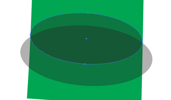
…then select both ellipses,…
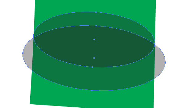
…go to the Pathfinder palette and click there the Minus Front button.
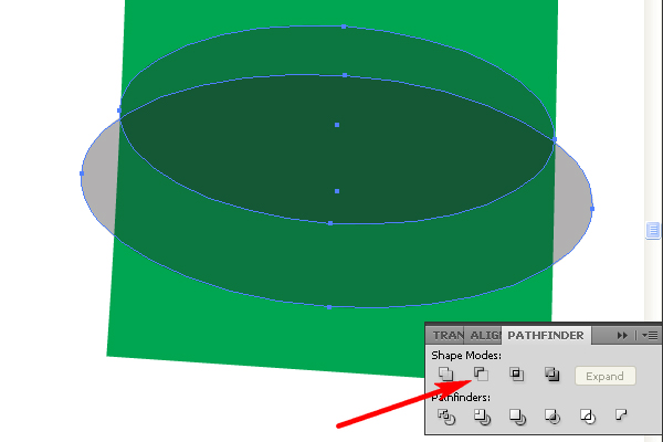
Change the opacity of the received path which will represent a rubber facing to 100%.
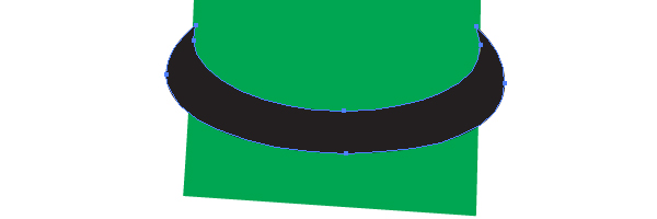
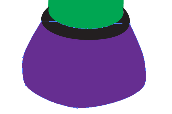
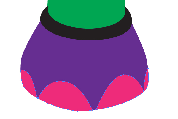
Step 5
Use the Pen Tool (P) to illustrate the violet path in the lower part of the main green tube of the tap.
And then picture four or more crimson paths as shown.
Step 6
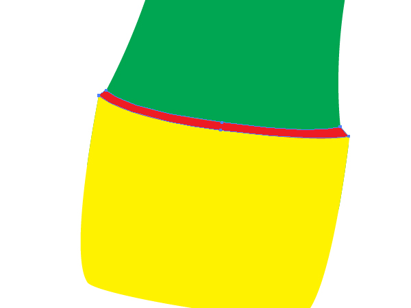
Draw the yellow path shown in the second end of the green tube.
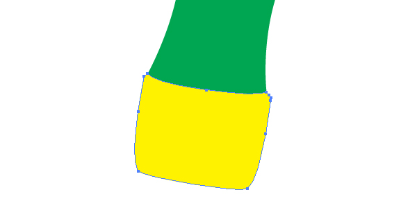
And draw the red thin path between the green and the yellow ones.
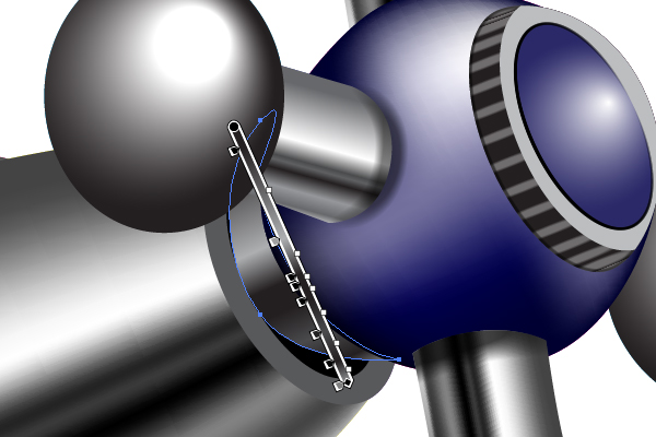
Step 7
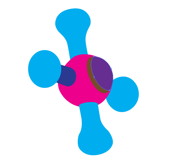
Let’s now produce the right tap. First, you need to illustrate a crimson circle by using the Ellipse Tool (L). After that you can change the shape of the circle slightly with the help of the Direct Selection Tool (A) in order to satisfy the chosen angle of view. See the image below for reference.

The levers are illustrated on other sides of each other.
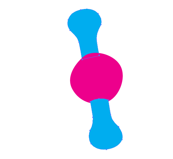
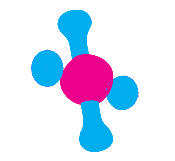
Attach the leftmost lever to the sphere of the tap. (The joining detail of the rightmost lever is invisible at such an angle of view).

Step 8
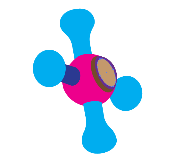
Illustrate the brown part of the sphere as shown in the image below.
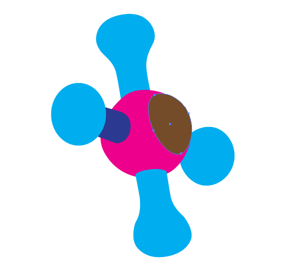
Then add the violet path to your artwork,…
…and add the light brown path as shown.
Step 9
Create now the following three paths.
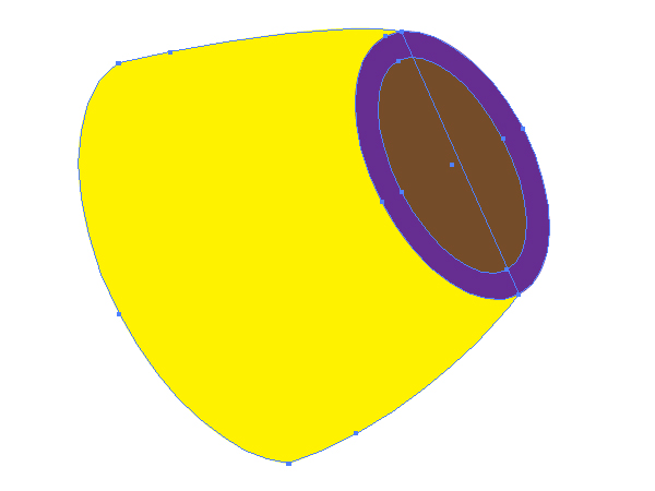
And you will receive the following image after these manipulations.
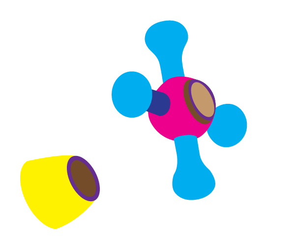
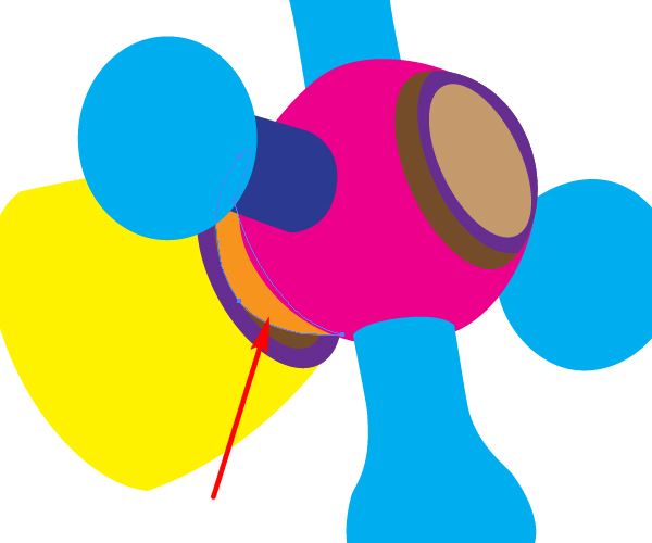
Now let’s imagine that we are the sanitary technician workers and we need to join these two details of a tap with each other. We can do it by using the small orange detail between them. Create it by using the Pen Tool (P).
Step 10
Take the Ellipse Tool (P) and sketch two other paths in the left end of the tap.
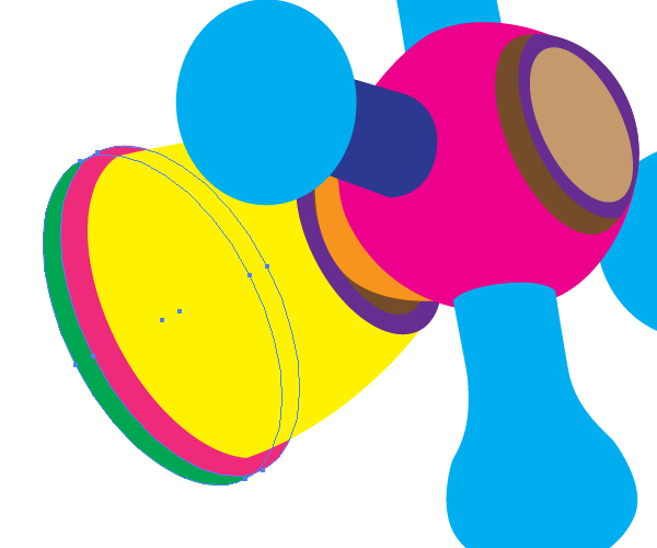
Illustrate the left tap the same way.

Step 11
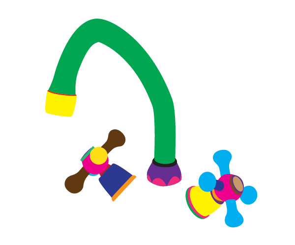
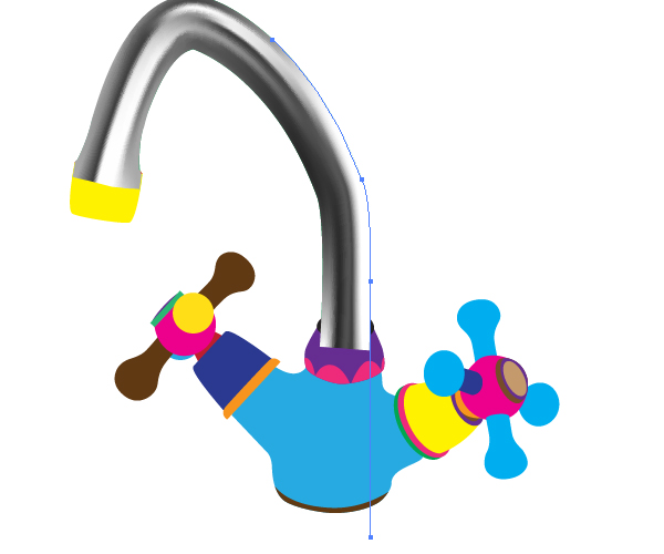
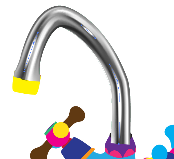
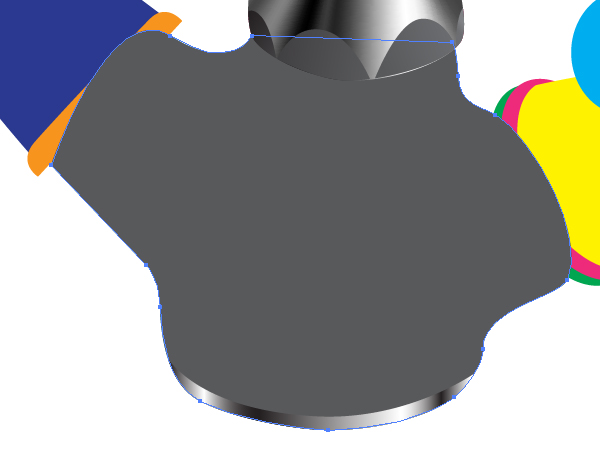
Let’s now see our artwork, and place the taps and the main tube details in the right positions in our workspace. Follow the image below.
Take the Pen Tool (P) again and picture a blue joining detail as shown below.
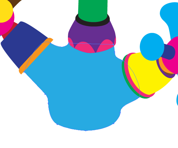
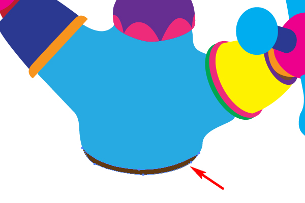
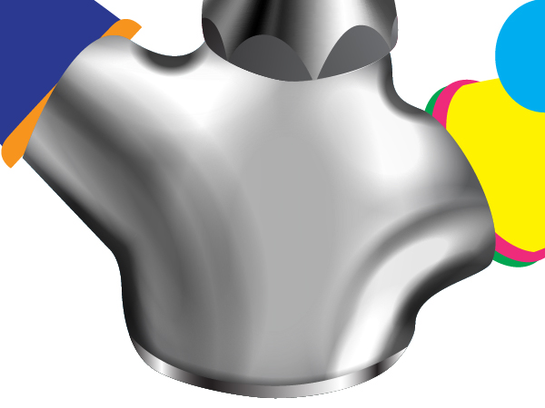
Now create a rubber support at the bottom of the full tap, and the main geometry image will be finalized.
Step 12
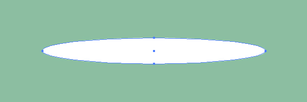
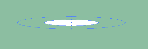
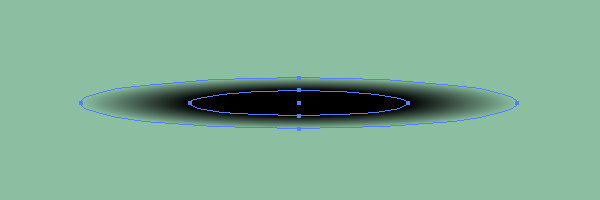
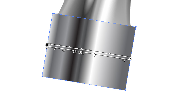
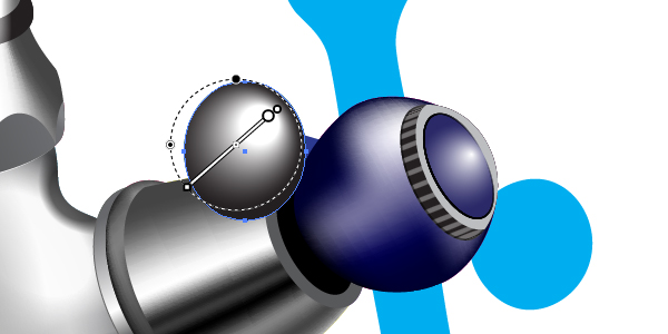
Let’s produce two necessary Art brushes. Grab the Ellipse Tool (L) and create an elongated elliptical path as shown in the image below. (The background is filled with olive for your convenience).
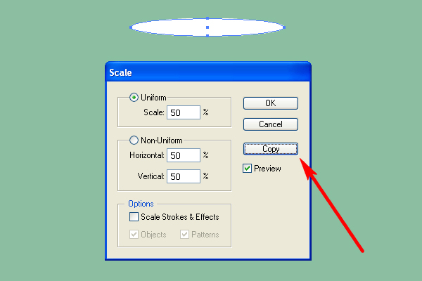
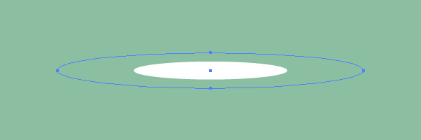
Go to Object > Transform > Scale and set there the values that you see in the diagram below. Then click the Copy button in this dialog box.
After that decrease the opacity of the biggest ellipse to 0.
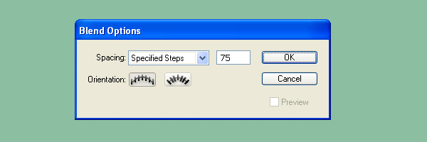
Go to Object > Blend > Blend Options, then set the Spacing to Specified Steps and the number of steps to about 75.
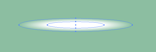
Select both ellipses,…
…and go to Object > Blend > Make (Command + Alt + B).
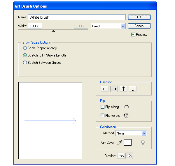
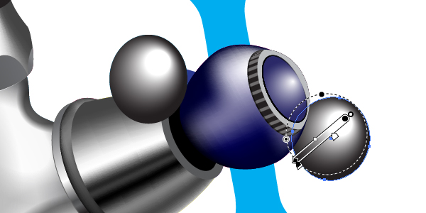
Step 13
Then drag and drop the received blend into the Brushes palette. Select the Art Brush option in the dialog box.
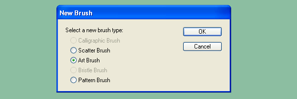
Set the items for the brush as shown in the diagram below. Now name the brush as “White brush.”
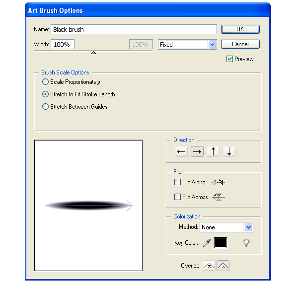
Produce the “Black brush” the same way.
Step 14
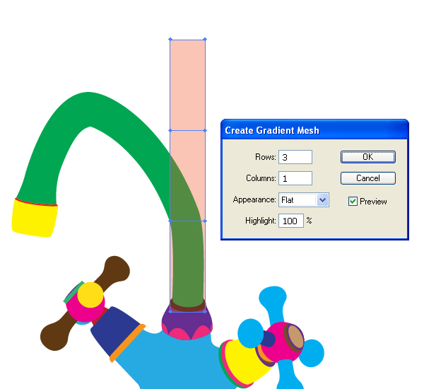
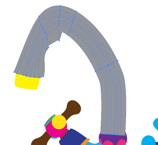
In order to paint the main green tube take the Rectangle Tool (M), first, and create a rectangle with a width approximately equal to the thickness of the tube or more. Then change the Opacity of the rectangle.
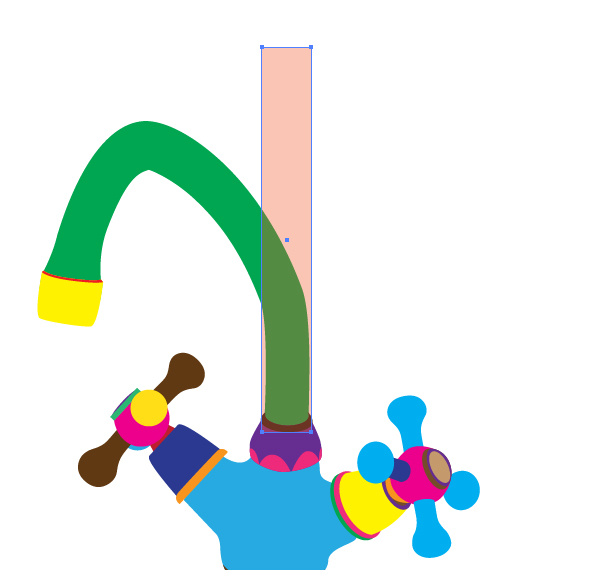
Now go to Object > Create Gradient Mesh and change the number of rows in the dialog box.
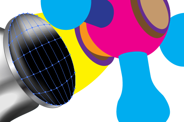
Step 15
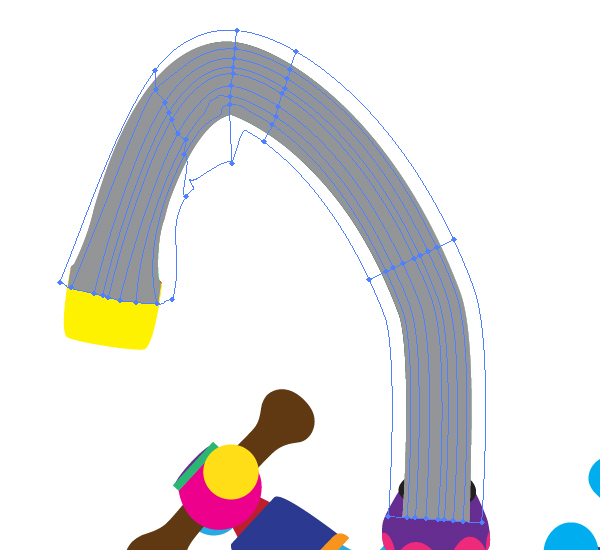
Take the Lasso Tool (Q) and select all the nodes of the gradient mesh, except for the two lowest ones.
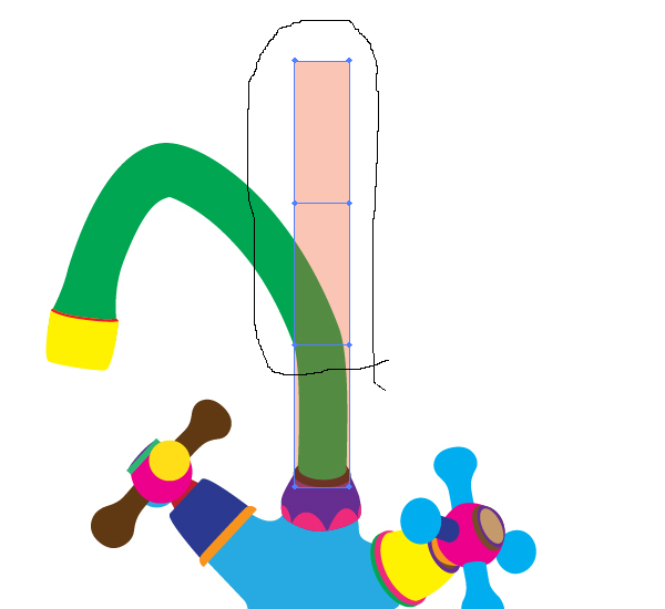
Now take the Rotate Tool (R), and make a rotation, as shown.
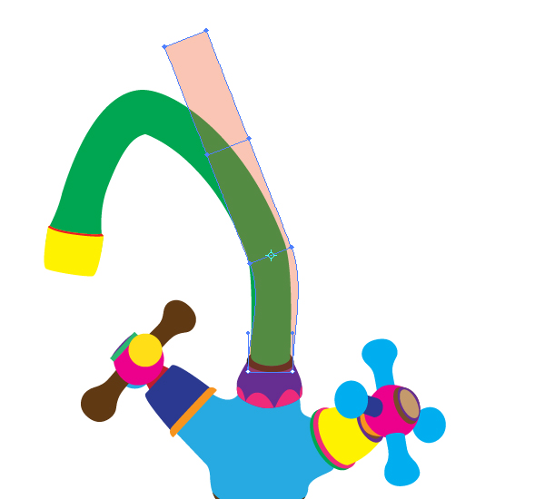
Take the Direct Selection Tool (A) and work on the nodes in order to achieve the approximate connection of the mesh with the green path. Pay attention that you need not achieve the precise connection. It will still be fine if your mesh is bigger than the green tube. See the following diagram.
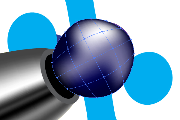
Step 16
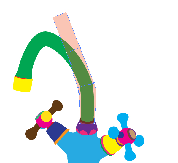
Change the Opacity of the mesh to 100% and change the color of it. Now take the Mesh Tool (U) and add the mesh nodes. Then work on the nodes with the help of the Direct Selection Tool (A).
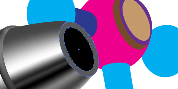
Select then the green main tube, go to Object > Arrange > Bring to Front (Command + Shift + Right Bracket key). Select both: this path and the mesh, and then apply Object > Clipping Mask > Make (Command + 7).
Now change the colors of the mesh in order to represent the distribution of light accurately.
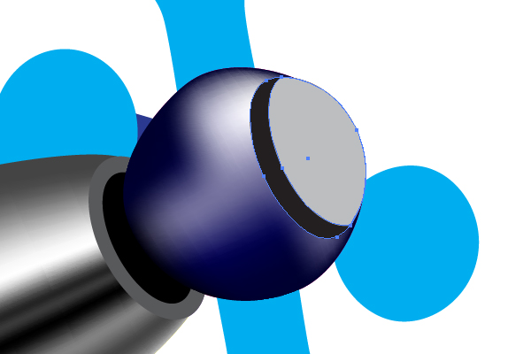
Step 17
Draw the path shown using the Pen Tool. Now apply the “White brush” to it. Crop the received path with a clipping path. and change the opacity if necessary.
Apply the “Black brush” to the following path the same way.
Repeat these manipulations in order to satisfy your feeling of beauty.
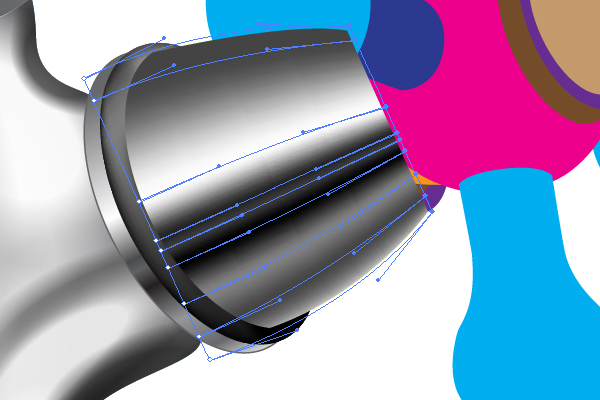
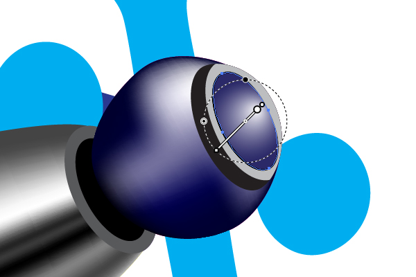
Step 18
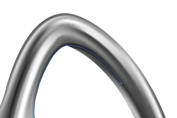
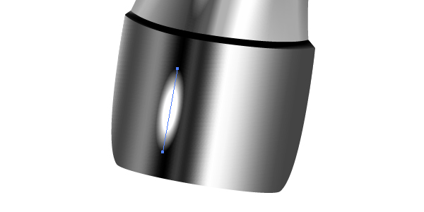
If we consider the angle of view, it becomes clear that the point shown in the diagram below must have its own light distribution.
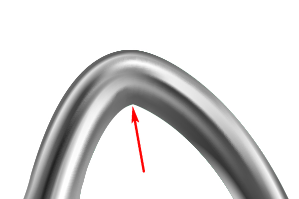
In order to achieve this we should apply the Art brushes for the following paths.
Step 19
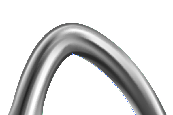
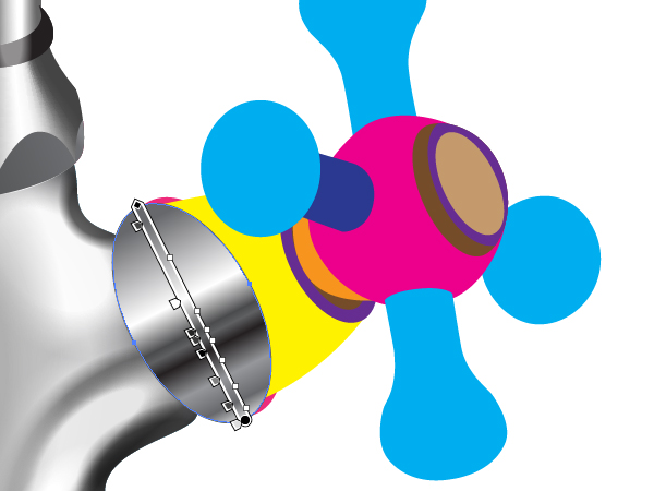
The metallic tube must have sharp light spots. So, you need to apply the “White brush” to the next shown paths.
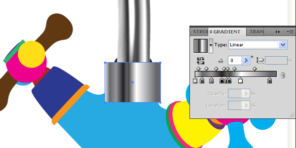
Step 20
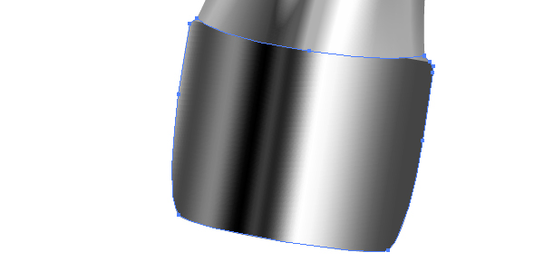
Take the Rectangle Tool (M) and illustrate a rectangular path over the yellow end of the metallic tube, and fill it with an angled linear gradient.
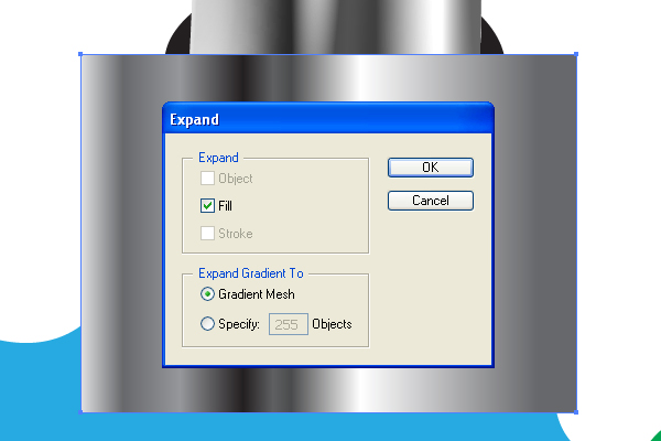
Then go to Object > Expand and expand this gradient to gradient mesh.
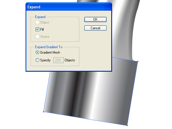
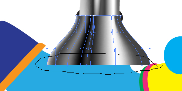
Create a clipping mask from the yellow end path by going to Object > Clipping Mask > Make, and crop the mesh with it.
Step 21
Apply the “Black brush” to the shown path,…
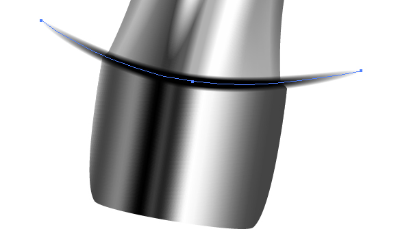
…and crop it with a clipping mask.
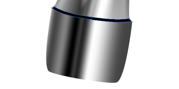
Now create a light spot.
Step 22
The violet path is painted the same way. First, take the Rectangle Tool (M), draw a rectangular path and fill it with a linear gradient as shown in the helpful diagram below.
Now expand the gradient fill to gradient mesh as you did before.
After that select the lower nodes of the mesh using the Lasso Tool (Q) and pull them out by going to Object > Transform > Scale. You should receive a picture the same as below.
Now crop it with a corresponding clipping mask.

Step 23
The semicircular facets are filled with corresponding angled linear gradients.

The rubber detail is filled with black,…

…and emphasized with a cropped path to which the “White brush” is applied.
Step 24
The lowest rubber detail is filled with a linear gradient as shown.

Fill the blue joining path with dark gray.
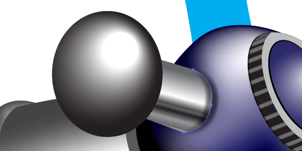
And add the shape to it by using the Art brushes. Up to this point in the tutorial you already know how to achieve this without assistance. Keep in mind only that your paths should represent not only the shape of the detail, but also the light distribution on it.
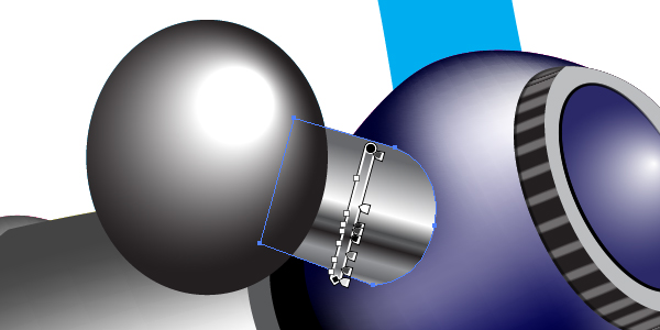
Step 25
The green end part of the right tap…
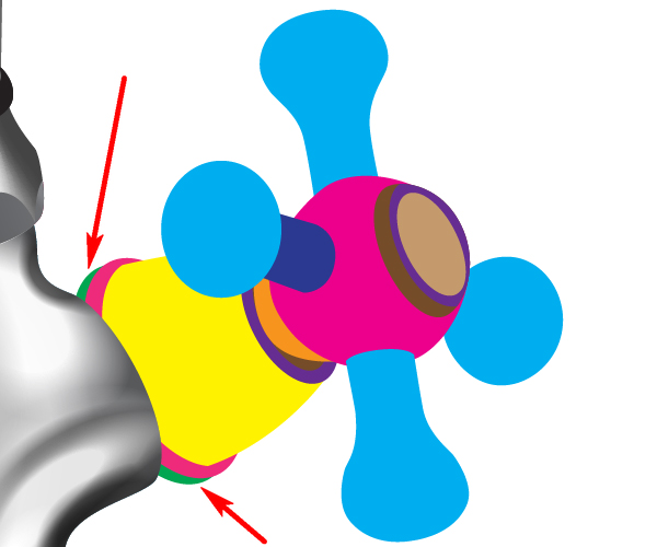
…should be filled with an angled linear gradient and should have a gray Stroke. I think that you know how to place any path in the top in the Layers palette, don’t you? I use the main geometry sketch in the bottom of the Layers palette because it is secondary only to the full artwork.
The next crimson path is converted into a mesh applying Object > Create Gradient Mesh. The light distribution can be seen in the following picture.
Step 26
The yellow path is another mesh created from the gradient filling. Create this yourself as you did earlier in this tutorial. The helpful diagram is shown below.
The next paths in the right tap is filled with the usual colors.
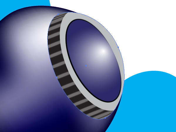
The crimson ball of the right tap is a mesh too.
Step 27
The top parts of the ball is filled with the usual colors as shown.
The elliptical path in the center of the top part is filled with a radial gradient.
Apply the “Black brush” to the Stroke of this path as shown in the image below.

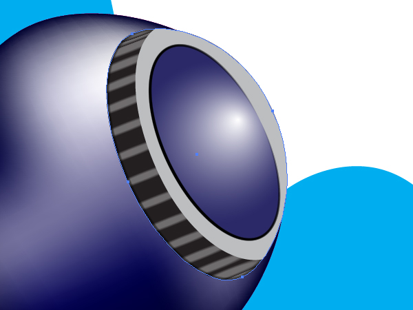
Step 28
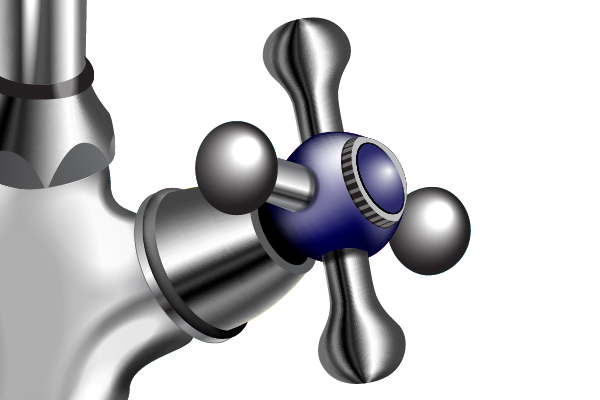
In order to create notches, first illustrate two linear paths and apply the “White brush” to both.
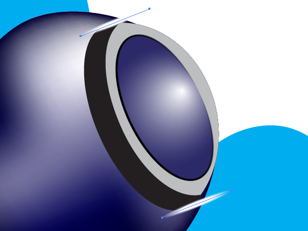
Then go to Object > Blend > Blend Options and set the Spacing to Specified steps and the quantity of steps to 15. Moreover, set the Orientation to Align to Page.
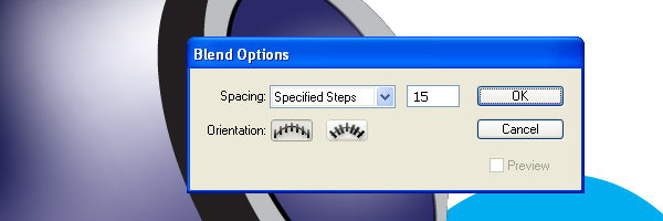
After that go to Object > Blend > Make (Command + Alt + B).
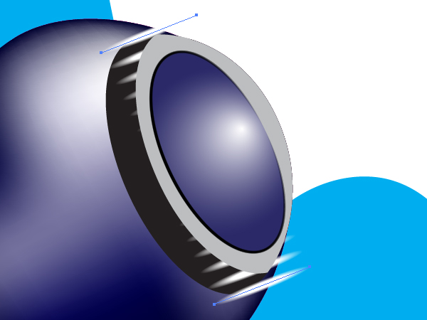
Take the Pen Tool (P) and draw the following path.
Drag and drop this path into the Blend group in the Layers palette. You should receive the following result:

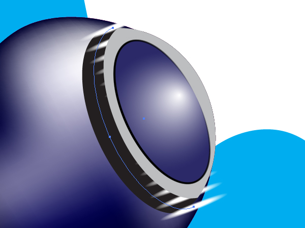
Change the opacity of the blend and crop it with a clipping mask.
Step 29
Apply the “Black brush” to the shown thin path, and crop it with that clipping mask too.
Fill the first blue lever with a radial gradient.
The opposite blue lever is filled with the same gradient.
The joining detail of the lever is filled with an angled linear gradient.
Apply the semitransparent “Black brush” to the shown path.
Step 30
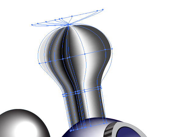
The top lever is painted with the help of a mesh cropped with a clipping mask. I think you already can do this yourself at this point in the tutorial. Follow the helpful diagram below. The mesh nodes beyond the bounds of the lever are not necessary. They are used for convenience to create the resulting mesh only.
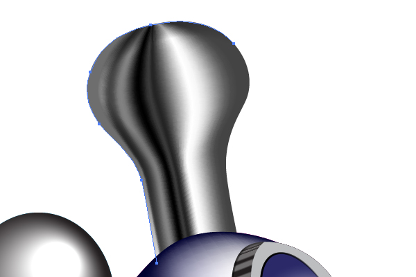
Shade the left side of the lever by applying the “Black brush” to the shown path.
Create the opposite lever.
The orange detail in the main geometry sketch, which attaches the ball to the tap, should be filled with an angled linear gradient as shown.
Step 31
The left tap is illustrated the same way.
Create the background using the mesh and your artwork will be finalized.
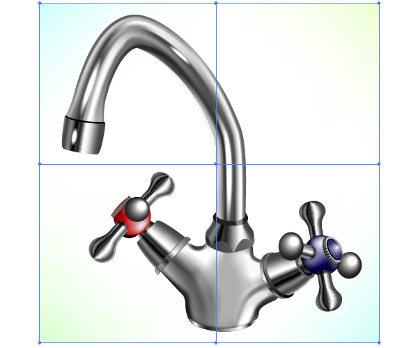
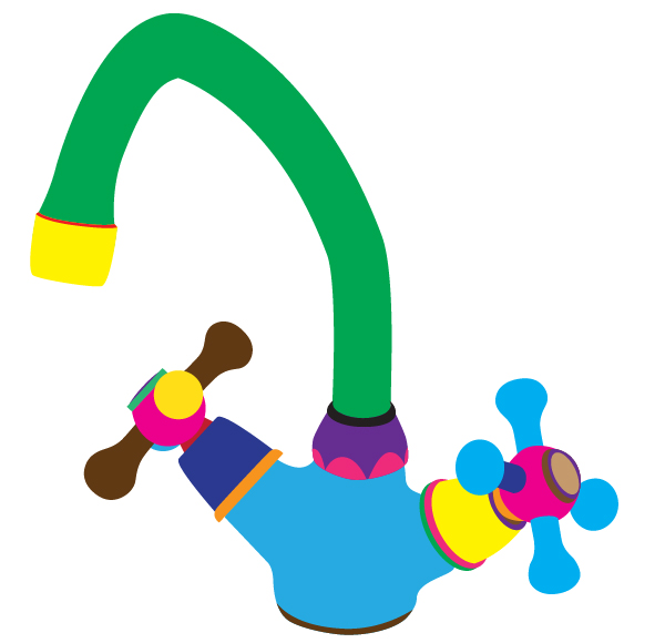
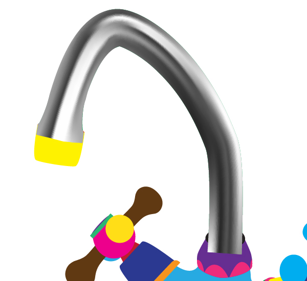
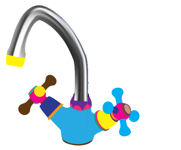
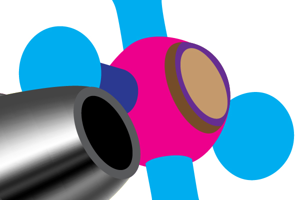
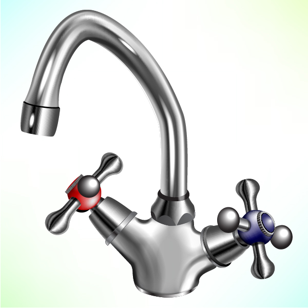
Conclusion
The final image is below.
{excerpt}
Read More