Visual Database Creation with MySQL Workbench
In today’s tutorial, you’ll learn how to use a visual database modeling utility to draw a database diagram and automatically generate SQL. Specifically, we’ll review how to use MySQL Workbench, a cross-platform, visual database design tool.
What is MySQL Workbench?
MySQL Workbench is a powerful tool developed by MySQL with three primary areas of functionality:
- SQL Development: Replaces MySQL query browser. Allows the user to connect to an existing database and edit and execute SQL queries.
- Data Modeling: Complete visual database design and modeling.
- Database Administration: Replaces MySQL administrator. Graphic interface to start/stop servers, create user accounts, edit configuration files, etc.
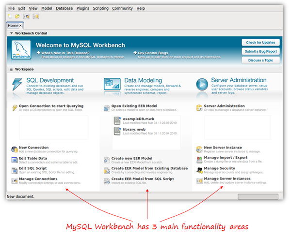
In this tutorial, we’ll focus on the Data Modeling aspect to create a database from scratch, and then have just a quick look at the SQL editor to execute our generated SQL script and create the database within MySQL.
MySQL Workbench is available for Windows, Linux and Mac OSX. There are two different editions: the Community OSS Edition and the commercial Standard Edition. The community edition is Open Source and GPL licensed, as you’d expect. It’s fully functional, and is the one we’ll be using in this article. The commercial edition adds some extra functionalities, such as schema and model validation or documentation generation.
Note: this tutorial is based on the Community OSS Edition version 5.2 (5.2.16), currently in beta release at the time of the writing (April 2010).
Planning our Database
To learn how to use MySQL Workbench, we’ll use a very simple database for online classes as an example. Suppose a group of teachers want to offer online classes for several subjects, using Skype or any other video conferencing software. For our little project, we have decided that we need to store the following information:
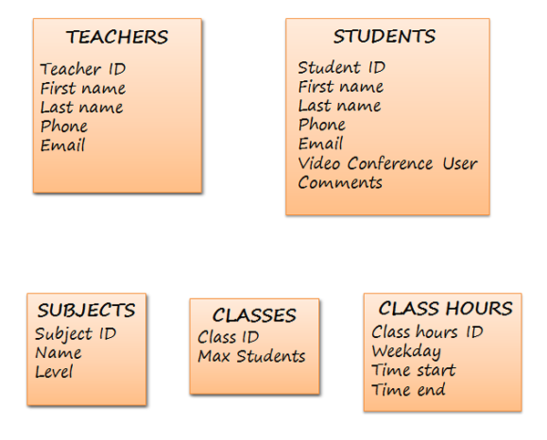
When drawing our diagram, we will need to know the relationships between these groups of data as well; so we better think about that now!
- One teacher can teach many subjects
- One subject can be taught by many teachers
- Each class has only one teacher
- One teacher can teach many classes
- One student can attend many classes
- One class has many students
- One class may have several hours (in a week)
- At one particular day and hour, there may be several classes
- A class is about one subject
- One subject may be taught in many classes
At this point, we have all the information we need to meet the star of this show…
Send in MySQL Workbench
It’s time to launch Workbench. In the data modeling part of the home screen, we click ‘Create new EER Model’, and the following screen appears:
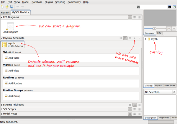
When we create a new database model, it contains the default mydb schema. We can rename it and use it as our DB schema. A database model can have several different schemas.
The catalog on the right will show every element in our schema, and allow us to drag and drop elements to diagrams if needed.
Having the separate sections for Physical Schemata and EER Diagrams, and the possibility to include several Schemas in one database model may be confusing. The next section explains these concepts and how they are related.
Clarifying Concepts
The physical schema contains all the necessary pieces to define the database: tables, columns, types, indexes, constraints, etc. This is what we are really defining. Every object added in the graphical model also shows up in the physical schema. It is, in fact, a visual way to define our schema.
We can have several schemas for the same database model in the same way we can have several databases in a MySQL server. Each schema will be a MySQL database. For example, in the next screen, we have two schema tabs:
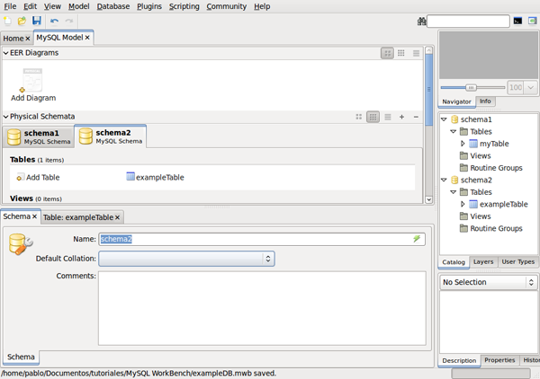
If we generate the SQL script, we will have two separate CREATE DATABASE statements – actually we will have CREATE SCHEMA which is just a synonym.
CREATE SCHEMA IF NOT EXISTS `schema1`;
CREATE SCHEMA IF NOT EXISTS `schema2`;
“EER stands for Extended (or Enhanced) Entity-Relationship. EER diagrams are just a way to model the data and the relationships between data using standard symbols”
They will be listed as databases within the MySQL server host when using SHOW DATABASES.
Now, what is an EER Diagram?. EER stands for Extended (or Enhanced) Entity-Relationship>. EER diagrams are just a way to model the data and the relationships between data using standard symbols. EER models can be complex, but MySQL Workbench uses only a subset of all possible graphical elements, because the purpose of this diagram (in this tool) is to have every element mapped to the physical schema.
We can use an EER diagram to define the whole database, or just small parts. For example, we can have a schema with five tables defined, and then create a new diagram to define two more tables using the visual editor. The diagram will contain only two tables, but those two tables will also be included in the schema, together with the previous five.
Creating our Tables
Back to our initial example; we have to rename the default schema by double clicking the name. At this point, we have two possibilities: we can start adding tables to our physical schema using the add table icon, or we can start an EER Diagram and add all the tables there.
I prefer to add a new diagram from the beginning and create my schema visually; however, in order to show how to do it with both methods, we are going to create the first two tables in the schema tab, and then continue with the EER Diagram.
When you click the Add Table icon, the table editor opens as a tab below:
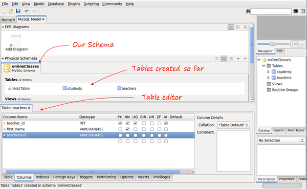
Using the table editor, we change the table name and switch to the columns tab (in the tabs below the editor) to enter our columns. We can choose the data type (there is a drop-down list with all the MySQL data types), assign default value, if needed, and we have seven checkboxes to mark any of the following properties:
- PK – Primary key
- NN – Not null
- UQ – Unique
- BIN – Binary
- UN – Unsigned
- ZF – Zero fill
- AI – Autoincrement
Go Visual
This is one way to add our tables, though we can also create them using the diagrams. If we click the Add Diagram icon now, we will begin a new, empty diagram, and that’s not what we want. We want the two tables that we just created to be in the diagram.
If we go to the menu, select Model/Create Diagram from Catalog Objects, now we have our diagram, and are ready to continue.
Select the table icon on the left; the pointer changes to a hand with a little table. Next, click anywhere in the canvas to create a new table.
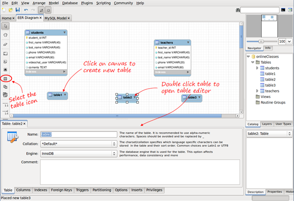
Now you just have to double click the table, and the editor tab appears to edit the name, columns, types, etc.- the same way as we did before.
After entering the column details for the new tables, we’ll be ready to start drawing the relationships.
Drawing Relationships
In the vertical tool bar on the left, we have six tools available to create relationships.
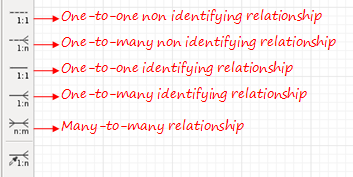
Don’t worry about the last one, we’ll explain it later. For the 1:1 and 1:n relationships, we have two different types of symbols: identifying and non identifying. What does that mean?
A relationship is considered identifying when one table is entirely dependent on the other to exist.
A relationship is considered identifying when one table is entirely dependent on the other to exist. A row in that table depends on a row in the other table. A common example is to have a separate table to store phones for users. It may be necessary to have it in another table, because there can be several phones for one user, but each row in that table is entirely dependent on the user – it belongs to the user.
You should be aware that relationships have some implications. If we want to create the physical tables in MySQL, relationships must be mapped in some way. There are a few rules to map relationships into tables:
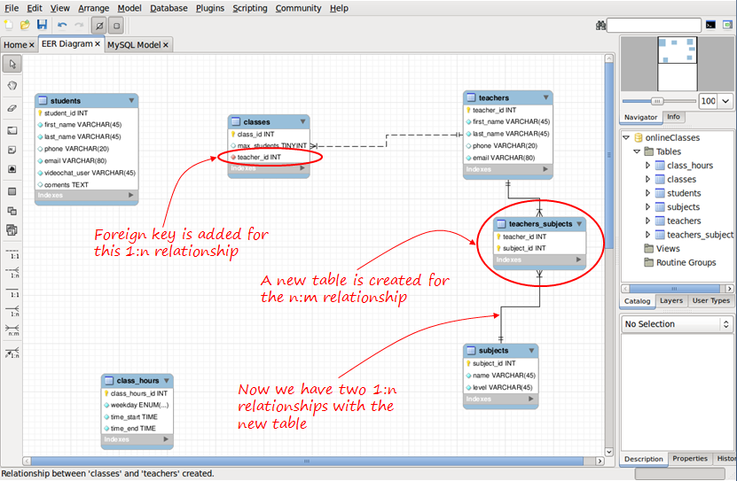
- 1:1 relationships. Primary key for one of the tables is included as foreign key in the other table.
- 1:n relationships. Primary key of the table in the ‘1′ side is added as foreign key in the table in the ‘n’ side.
- n:m relationships. A new table (join table) is created. The primary key is composed of the primary keys from the two original tables.
Identifying relationships are typically used for the join tables created from a many-to-many relationship. These new tables are entirely dependent on the two original tables.
Also, in the case of 1:1 and 1:n identifying relationships, the foreign key introduced will be part of the primary key for that table, forming a composite primary key.
The good news is that MySQL Workbench knows these rules better than most of us. We just draw our lines, and the foreign keys or join tables will be automatically be created. We can also choose to do it manually, as we’ll see shortly.
To draw a relationship, click the icon, and then click the two tables to relate. For one-to-many relationships, click on the “many” side table first, and then on the “one” side table. Let’s see how to do it for the n:m teachers-subjects relationship, and for the 1:n teachers-classes.
The default name assigned for the foreign keys, and for the join tables can be changed globally in Edit/Preferences/Model Tab, or only for the present project in Model/Model Options.
If we don’t want tables and foreign keys to be generated in this way, we can use the mysterious “sixth symbol.”

The “sixth symbol” creates a relationship using existing columns, meaning that you have already included the necessary foreign keys in your tables and created the necessary join tables (n:m mapping tables). Since we’ve already created these Join tables, we don’t need n:m relationships; only 1:n is available.
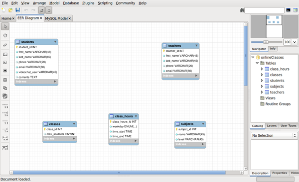
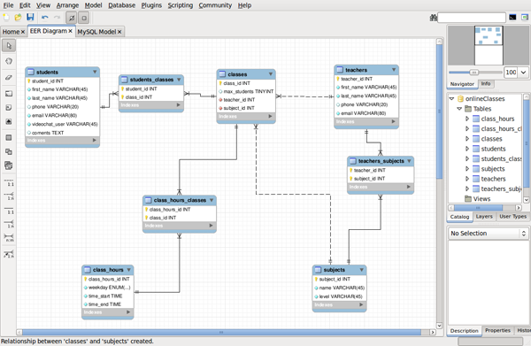
When we have all our relationships defined, our diagram should looks like so:
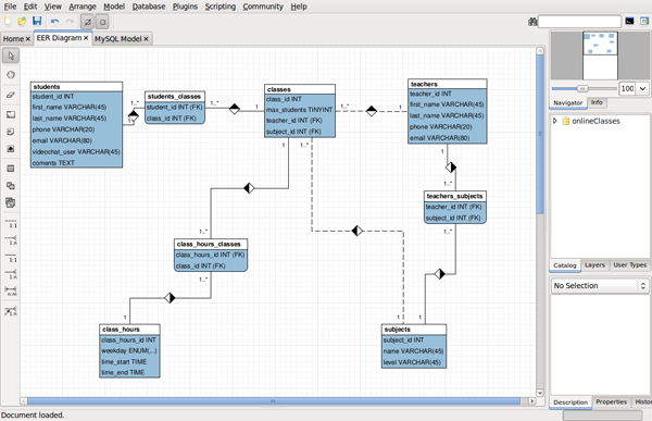
Be aware that we have been using the default MySQL Workbench notation for the diagrams, but you can change that in Model/Object Notation and Model/Relationship Notation. This is an example of our model in Classic notation:
At this point, our model is ready, and we can generate the SQL to create the MySQL database.
Generating SQL
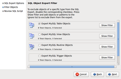
Select File/Export/Forward Engineer SQL CREATE Script. We are only three wizard screens away from generating our file!
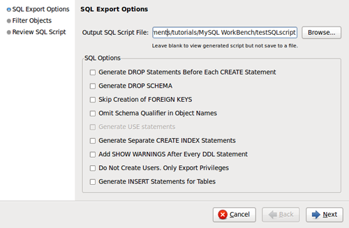
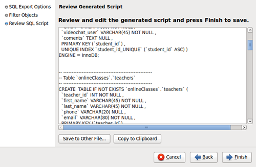
We even have the option to review and edit the generated SQL before saving it:
And that’s it. Clicking finish, the SQL script will be generated and saved. Now, we can use it in any way we wish. We can load it using the command-line mysql client:
mysql> SOURCE scriptName.sql
Or, we can use MySQL Workbench to finish the work, connecting to our MySQL server and running the script.
Connecting to a MySQL Server
Select Database/Manage Connections from the menu, and click NEW.
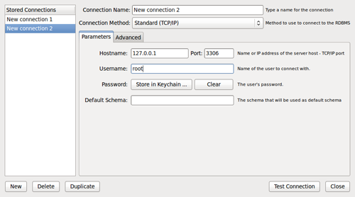
If you don’t want to set the password here, you’ll be prompted for it when needed. Click “Test Connection” to check if your parameters are correct, and then click close.
Now, to load the script, we’ll use the SQL editor. In the main menu select Database/Query Database; a window prompts you to select a connection, and then the SQL editor tab opens.
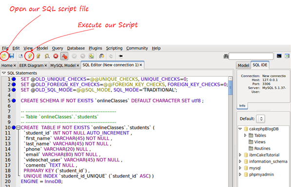
Now click the lightning icon to execute the SQL script, and your database will be generated!
We could also have generated the MySQL database directly from the model, without referencing the actual file, using Database/Forward Engineer from the menu; however, I find it useful to generate the script and then use it how I wish.
Conclusion
MySQL Workbench is an impressive tool. We have only seen a few basic possibilities in the data modeling part, and only peeked at the SQL editor in the second half of this tutorial. We learned how to create a database visually and draw diagrams that can be kept as documentation. You can export the diagrams as a PNG, SVg, PDF or PostScript file. Thanks for reading, and let me know what you think!
Thanks, that was very helpful.
Ronen.
Great tutorial – helped me with an issue I was having. Thanks for posting it.
Thank you!
The best tutorial!