In this Adobe Illustrator tutorial we are going to create a vector illustration of a twisted Filmstrip. Using the combination of a few very useful tools, such as the Pen Tool, Extrude & Bevel 3D effect and the Blend Tool, we will turn a simple curve into a beautiful Filmstrip. We learn to emphasize the realistic look of the illustration by applying necessary gradients. Let’s get down to business!
Step 1
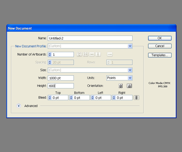
Create a new Illustrator document. Set the dimensions to 1000 pixels by 600 pixels.
Step 2
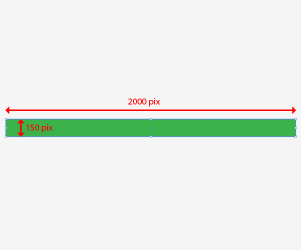
Let’s start with creating a filmstrip symbol. We’ll apply that symbol to the 3D filmstrip we will create later. First, we have to establish the width of the filmstrip. In this tutorial it will be 150 pixels. This detail is actually very important for creating a 3D object.
Grab the Rectangle Tool (M) from the Tool Panel and click somewhere on the working area. The Rectangle option box will appear. Set the value for the width to 2000 pixels and the height to 150 pixels. It will create a very long strip.
Step 3
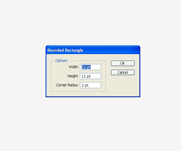
Now we need to create small holes on both sides of the strip. Select the Rounded Rectangle Tool from the Tool Panel, click on the working area and set the values as you can see in the picture below.
Step 4
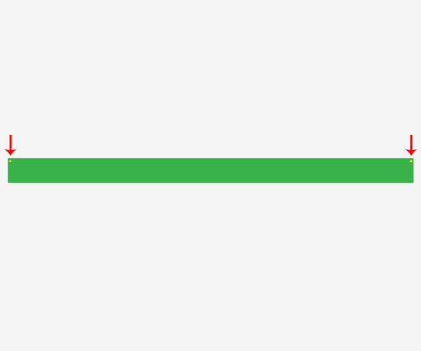
Place the small rectangle in the top left corner of the green strip. Hold the Alt key on the keyboard, then click on the yellow rectangle and drag it to the right (do not forget to hold the Shift key on the keyboard for straight dragging).
Step 5
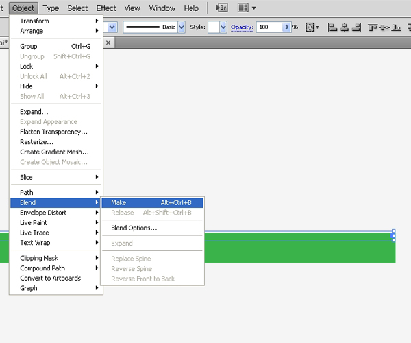
Select both the yellow rectangles, then under apply Object > Blend > Make.
Step 6
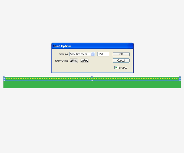
Select again Object > Blend > Blend Options. Set Spacing to Specified Steps in the dropdown menu, then set the Spacing value to 100. This will create many yellow rectangles.
Step 7
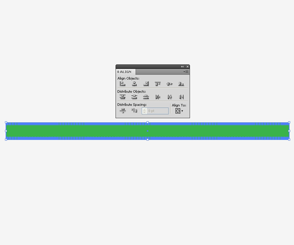
Duplicate (Command + C, Command + F) the rectangles we have just created and move the copies downwards. Select both rows of the yellow rectangles, expand them (Object > Expand) and group them (Command + G). While holding the Shift key on the keyboard, select the green strip under the Align Panel, hit the Horizontal Align Center, then Vertical Align Center.
Step 8
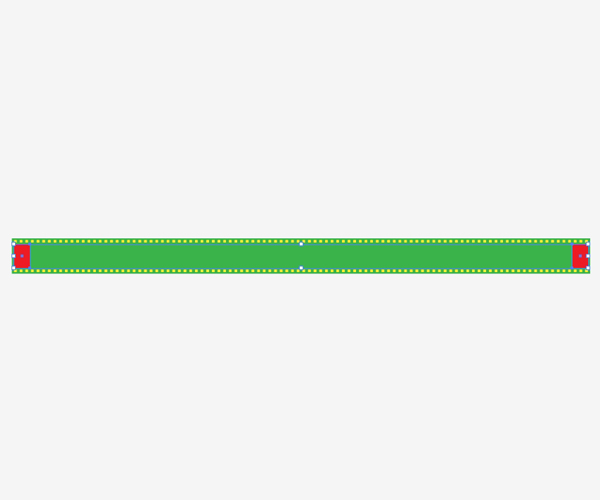
Grab the Rectangle Tool (M) one more time and create a rectangle with the dimensions 70px by 201px. Place it on the left middle part of the green strip. Hold the Alt key on the keyboard and drag the rectangle to the right. This will create a copy of the red rectangle. Don’t forget to hold the Shift key on the keyboard for straight dragging.
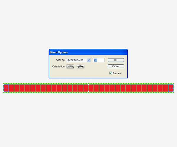
Step 9
The Blend Tool will help us one more time to create the red rectangles we need. Select both red rectangles and under the Object select Blend > Make. Select again the Object > Blend > Blend Options. Set the Spacing to Specified Steps in the dropdown menu, and set the value for Spacing to 30.
Step 10
Don’t forget to align the rectangles with the rest of the strip using Horizontal and Vertical Align Center under the Align Panel, just like we did with the yellow rectangles.
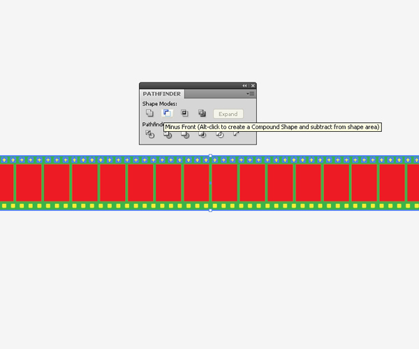
We are almost done with the filmstrip symbol. All we need to do is to create actual holes on the filmstrip. We need to Ungroup (Shift + Command + G) the rows of the yellow rectangles. First select the upper row of the rectangles and the green strip. Under the Pathfinder Panel hit the Minus Front button.
Step 11
Repeat the previous step with the lower row of yellow rectangles. You should end up with something like this:
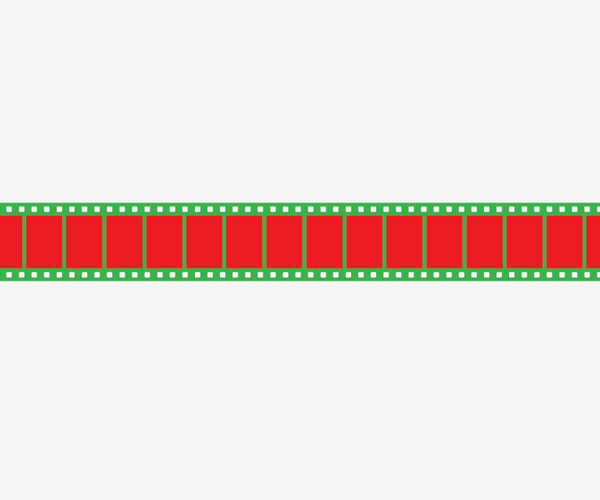
Step 12
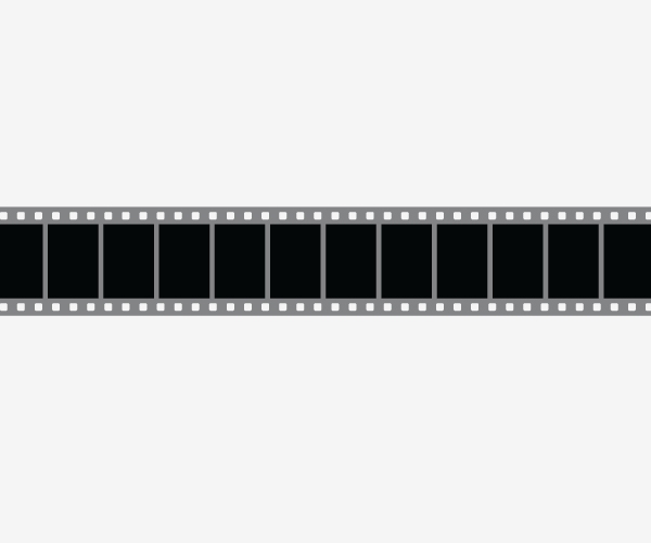
We have to expand the red rectangles as well (Object > Expand), then change the colors of the filmstrip as shown.
Step 13
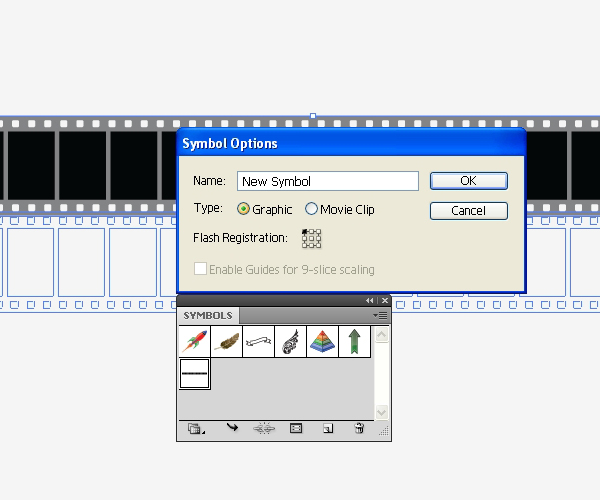
Select all the elements of the filmstrip and Group them (Command + G), grab the filmstrip and drag it into the Symbol Panel. In the Symbol Option box select Graphic.
Step 14
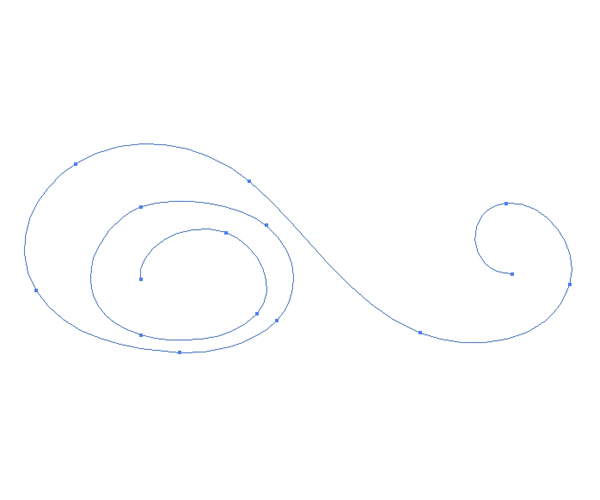
Now we’ll create a nice and simple curve. Select the Pen Tool (P) from the Tool Panel and create a curve as shown in the picture below. Set the Stroke color to gray and remove the Fill color.
Step 15
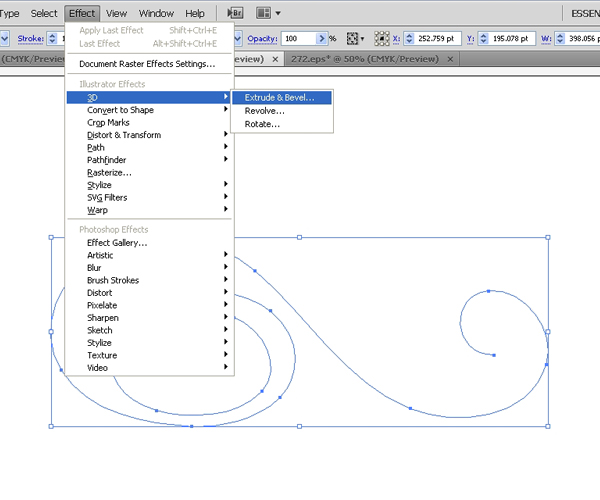
Under Effect select 3D > Extrude & Bevel.
Step 16
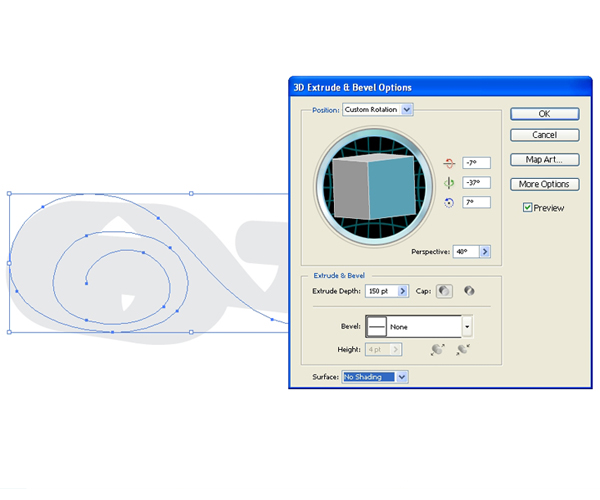
Set the Extrude Depth to 150 (this is the width of the filmstrip we established at the beginning of this tutorial). Don’t forget to adjust the Perspective (object without perspective looks a little bit distorted). We will set it to 40. There is one more quite important thing. For the Surface select No Shading. This way we will avoid creating many tiny parts of the 3D object.
Step 17
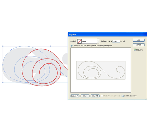
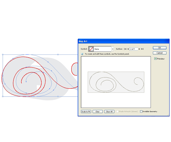
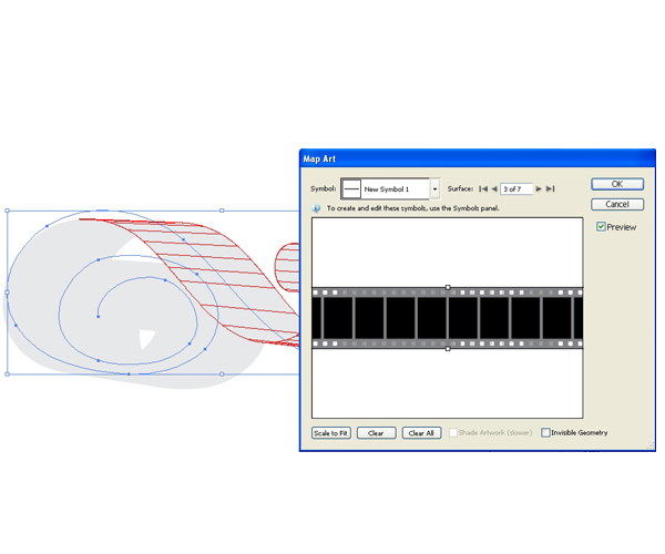
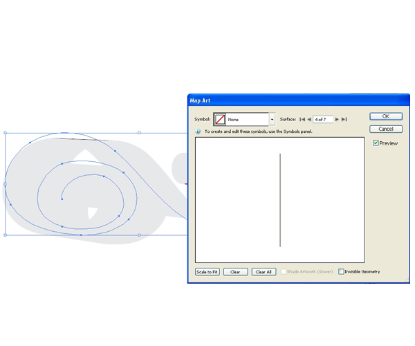
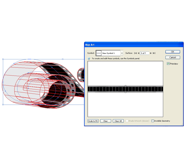
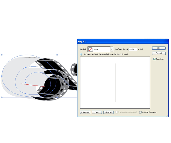
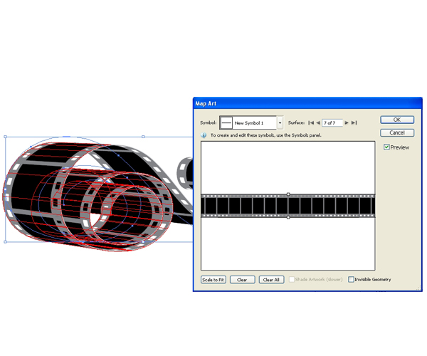
In this step we’ll apply the filmstrip symbol we created earlier to the 3D filmstrip. Under the Extrude & Bevel Option Box hit the Map Art button. Don’t forget to check the Preview box in order to be able to adjust the illustration easily.
Under the Map Art Options we will apply the filmstrip symbol we’ve created earlier to specific sides of our 3D filmstrip. Switch between the Surface of the 3D filmstrip and apply the filmstrip symbol to the sides: 3, 5 and 7 from the Symbol dropdown menu.
Step 18
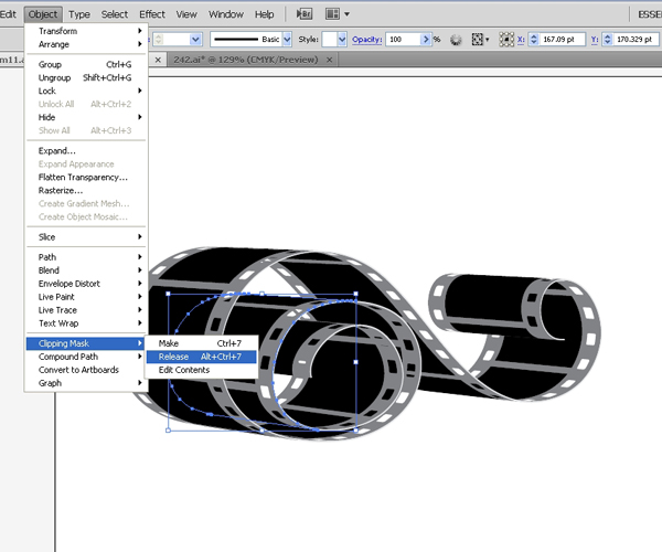
Now we need to expand our 3D filmstrip in order to apply nice color gradients. Under the Object hit Expand Appearance. Ungroup (Shift + Command + G) the filmstrip. Since our illustration contains many parts, be ready to ungroup the object several times. It will allow us to apply color gradients to each part separately. You may also have to remove the clipping mask in order to separate all the parts. To release the clipping mask hit the Alt + Command + 7 shortcut on the keyboard, or simply select Object > Clipping Mask > Release.
Step 19
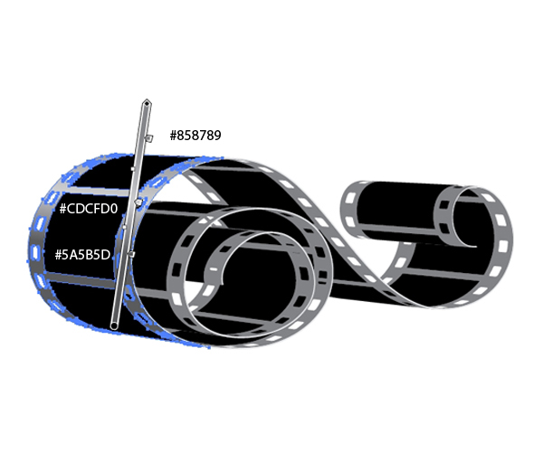
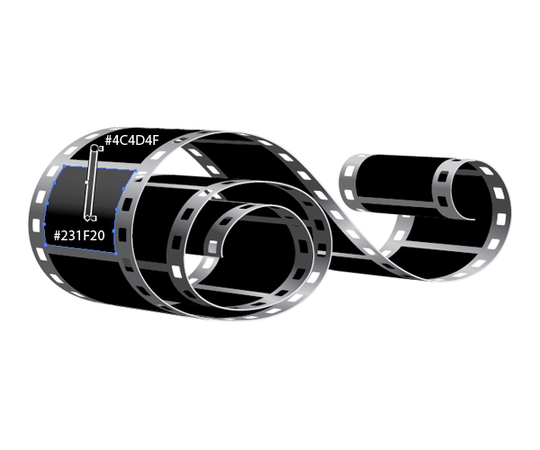
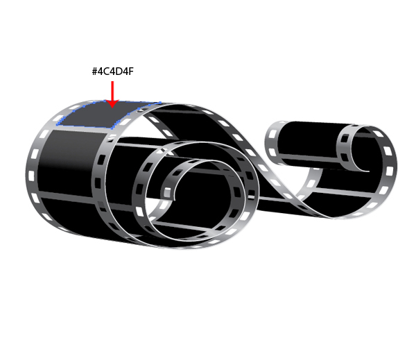
After we are done ungrouping the filmstrip we can start to apply color gradients. There is one thing we should keep on mind though. Color gradients will help us to make a realistic illustration. Now we have to focus on the parts of the illustration that need to be in the shadow and the parts we need to highlight. To each gray part of the filmstrip (frame of the filmstrip) apply a gray to light gray gradient, and to the black parts we need to apply a black to gray gradient. Light colors in the gradients will create highlights for the object.
Let’s start with the gray parts.
Step 20
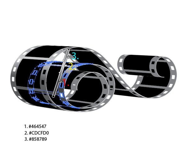
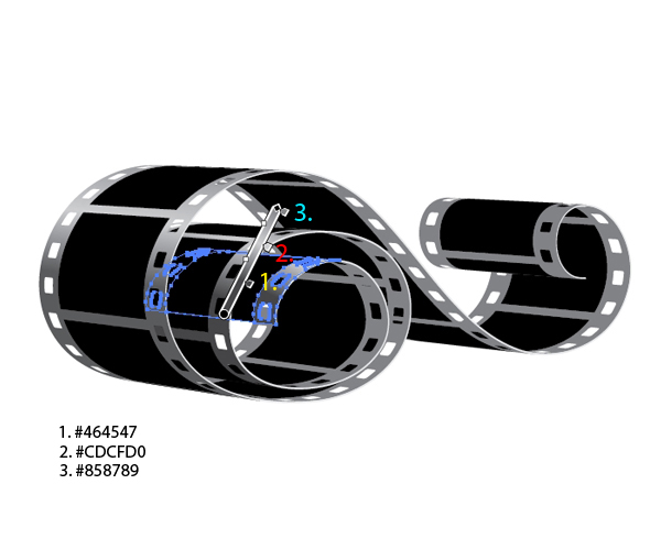
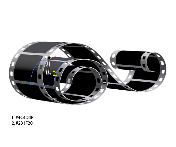
For the black parts (squares) we need a black to gray gradient. We don’t need the gradient for all the squares. With the black to gray gradient we’ll try to simulate the highlight on the black parts.
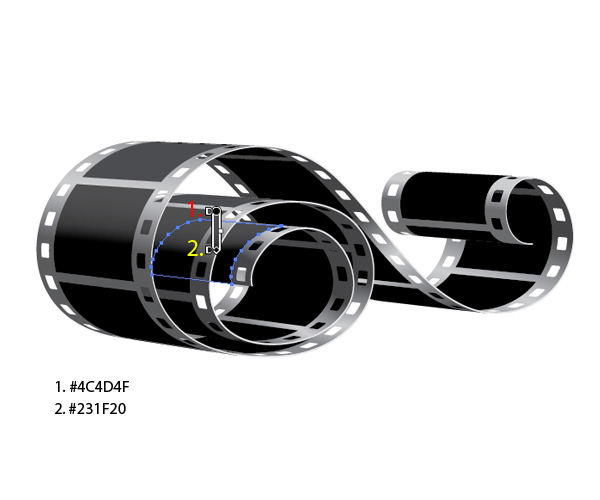
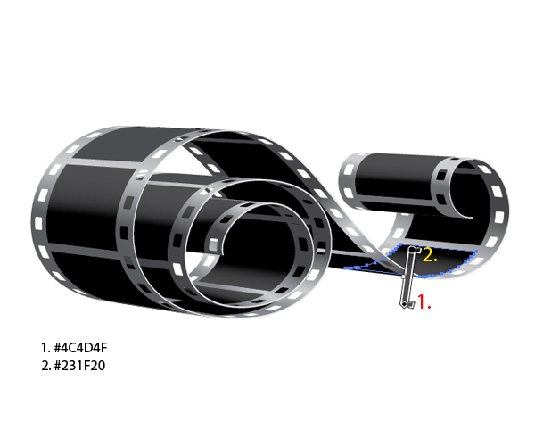
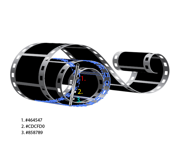
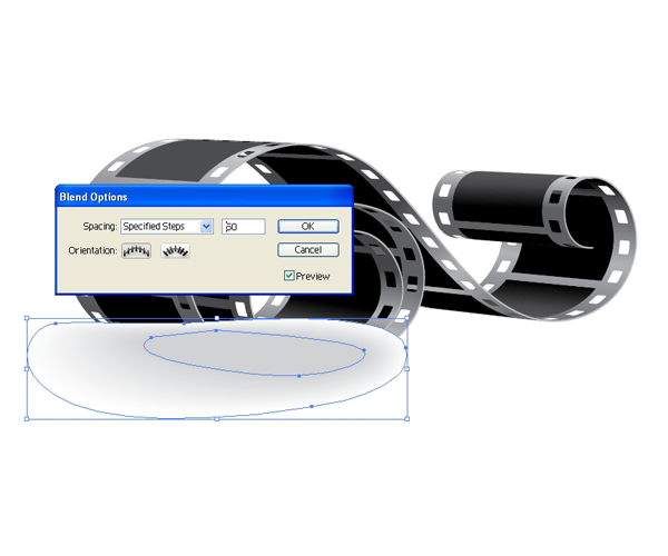
Step 21
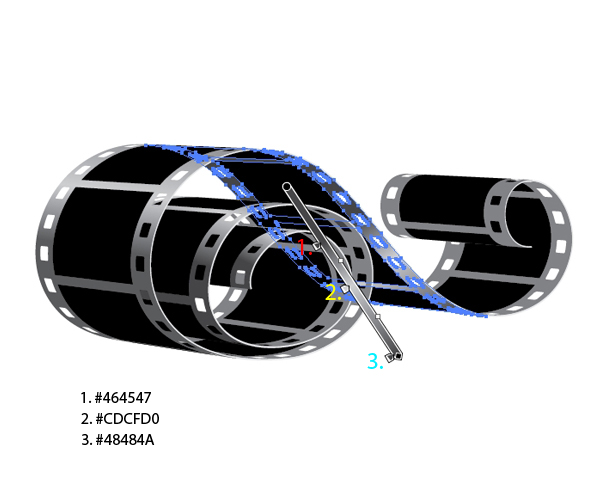
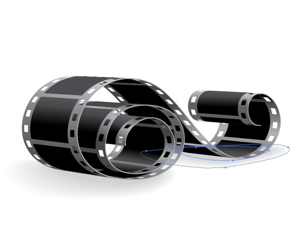
In this step we’ll try to create two shadows of irregular shapes. To do that we’ll need the Blend Tool. Grab the Pen Tool (P) from the Tool Panel and create a shape as shown. You’ll notice that this shape contains four anchor points. Set the Fill color to gray (#D1D3D4).
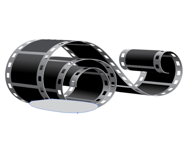
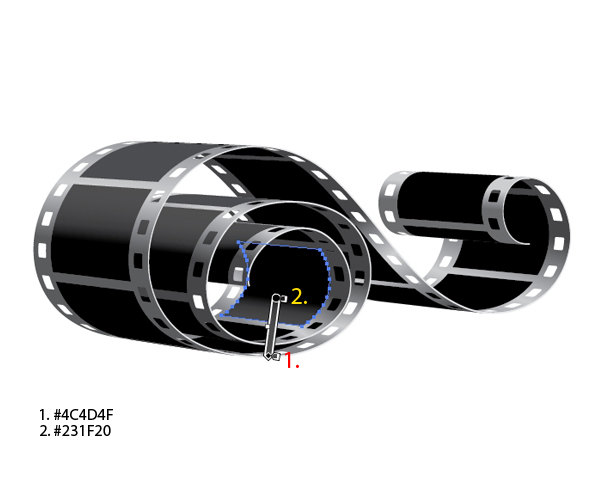
Step 22
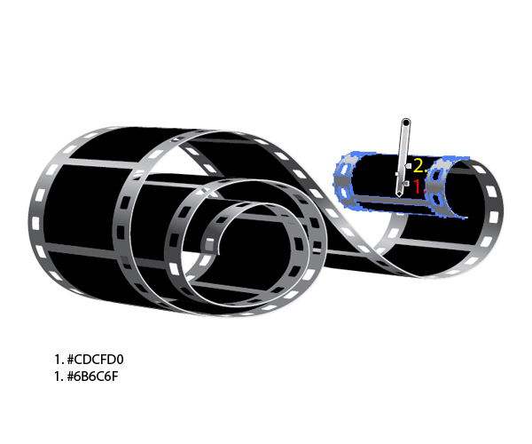
With the Pen Tool (P) draw one more shape. Make sure to create it with just four anchor points. Set the Fill color to white (#FFFFF).
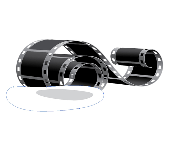
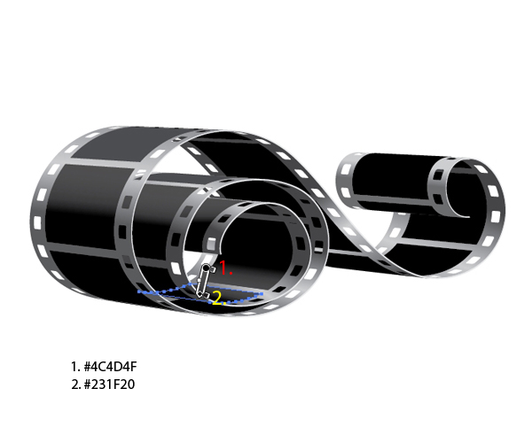
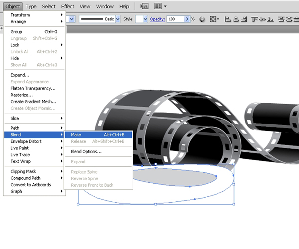
Step 23
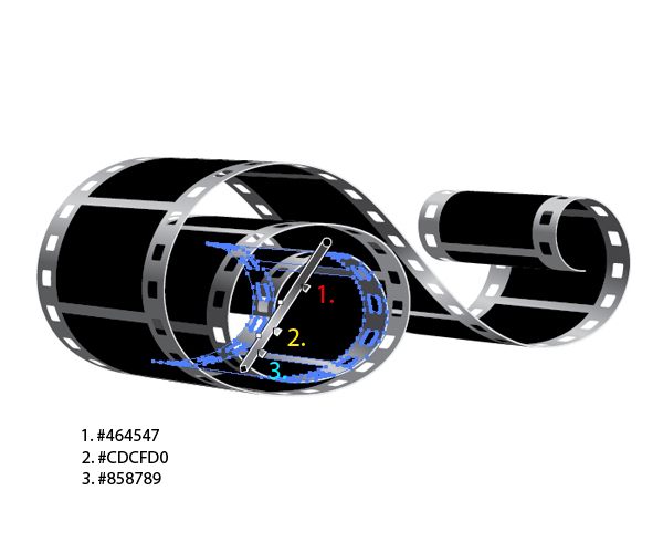
When you are blending vector paths the number of anchor points are very important. You have to make sure the paths contain the same number of anchor points. Otherwise, you wont be able to create a smooth transition between colors. Select both shapes and under the Object select Blend > Make. Then, select Object > Blend > Blend Options and set the value for Specified Steps to 50.
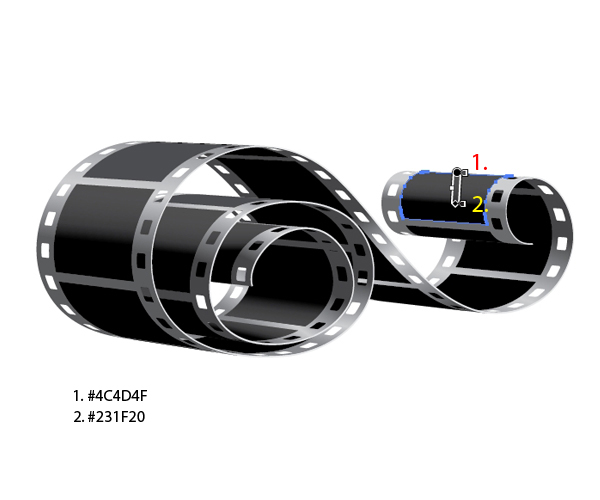
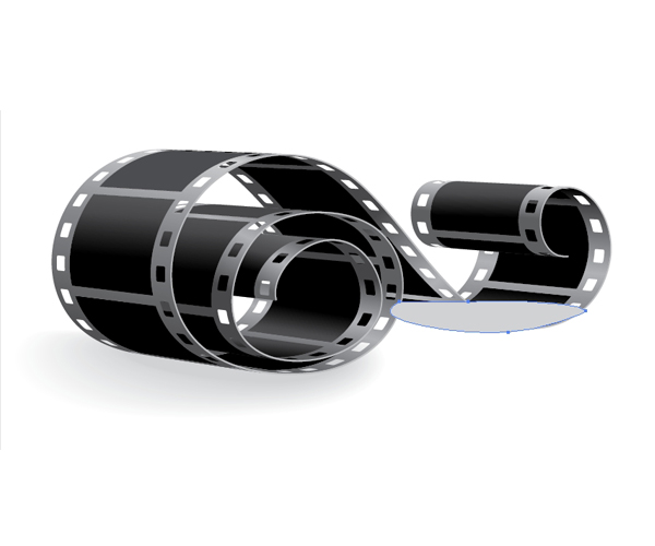
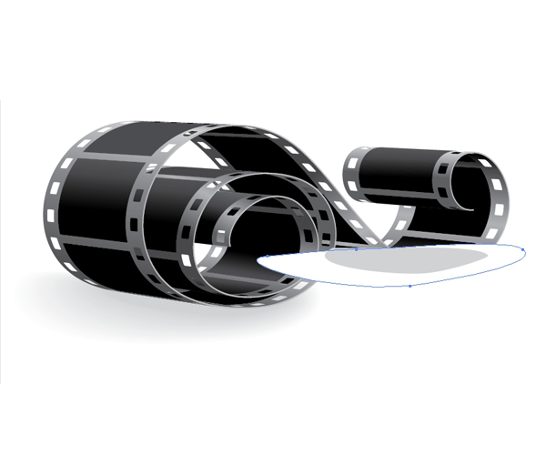
Step 24
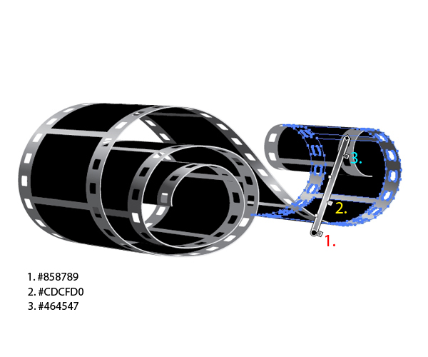
Send the shadow we’ve just created to the back (Shift+Command _+[). Using the same technique create the shadow for the other part of the filmstrip. Just make sure to blend two shapes with exact same number of anchor points.
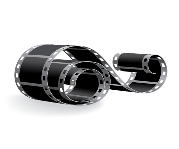
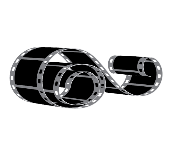
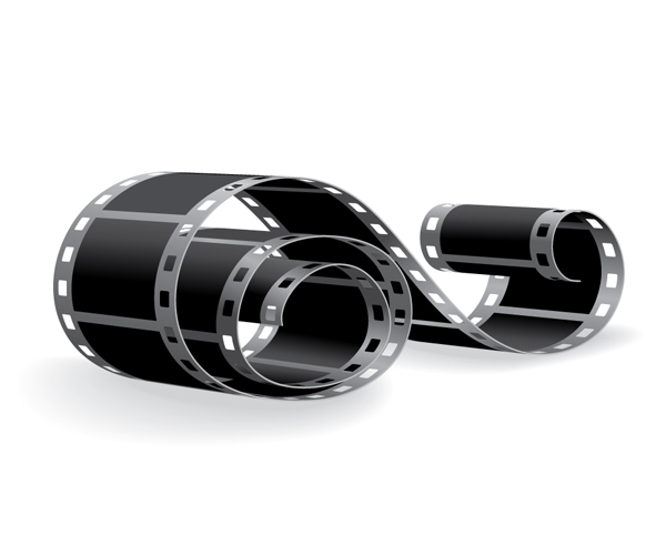
Final Image
And we are done! With the combination of a few very useful tools and shapes we have created an attractive filmstrip. Try out this technique and create a filmstrip in different positions. Feel free to be creative and play around with the perspective. If you have any questions or comment please post them in the comments section below. I hope you like the tutorial. Thank you for following along!
{excerpt}
Read More