In this tutorial you’ll learn how to create nice looking particle-generated 3D text. Instead of faking the 3D look, let Particular draw whatever shape or design you want in actual 3D space and bring your fancy titles to a new level!
Tutorial
Introduction
I understand that it’s obviously better to use a 3D application to create 3D stuff. But I believe there are people who don’t know how anything about such applications or perhaps don’t have the time to learn new things. Anyway, you can use this technique to “draw” pretty much any shape in 3D. And yea, I know that there isn’t hardcore science behind this, but in my opinion the end result looks very good.
Understanding the screenshots in this tutorial might be a bit difficult at times (I have 24″ monitor and had to crop them a lot), so I uploaded the original screenshots and you can download them in a .zip file here.
Step 1
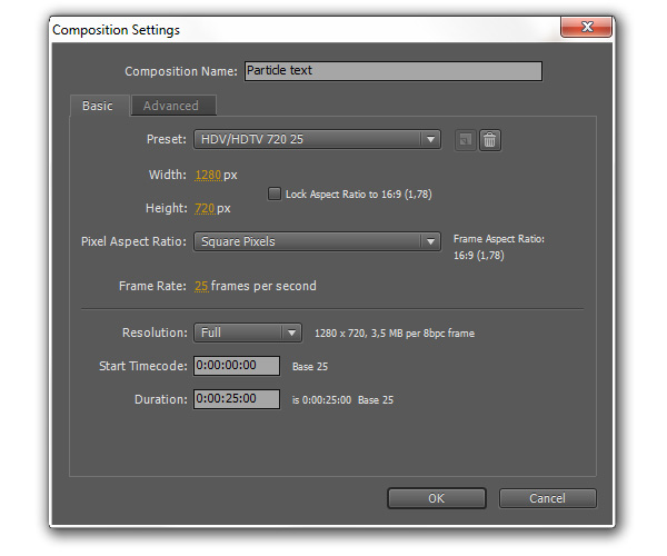
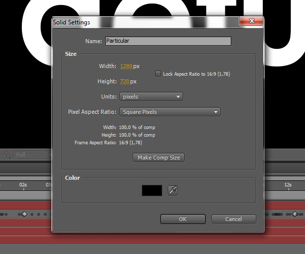
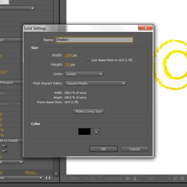
Create a new composition called “Particle text”, make it 1280×720 25 fps and 25 seconds long.
Step 2
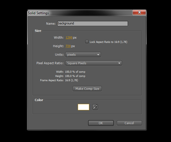
Create a new solid layer called “background” and make it white.
Step 3
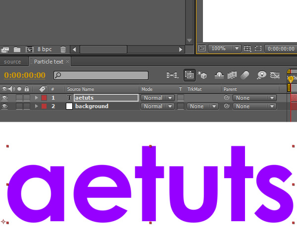
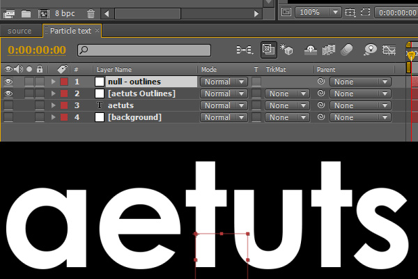
Create a new text layer (use any font you like) and type “aetuts”.
Step 4
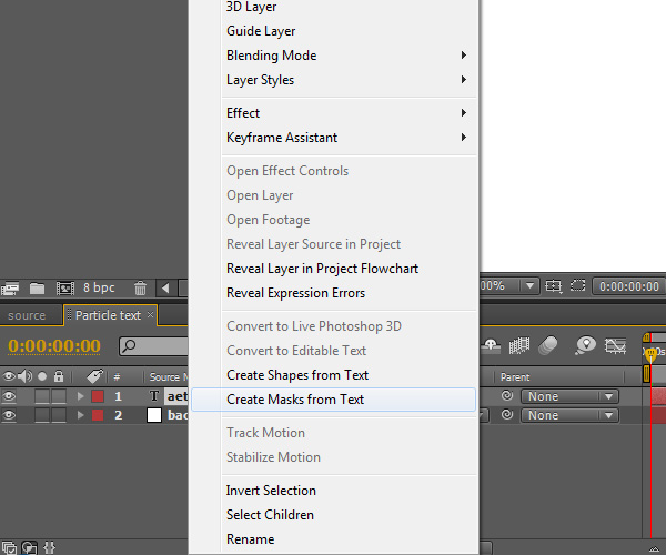
Right click on the text layer you’ve just created and select “Create masks from Text”.
Step 5
Create a new null object and call it “null – outlines”.
Step 6
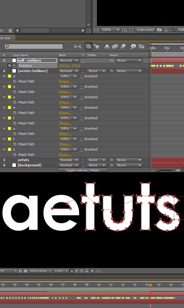
Now we need to take the mask points and use them to animate the “null – outlines” so it follows the mask paths and can be used later for the X,Y coordinates in Particular. Click on the “aetuts Outlines” layer that was created by AE, hit “M”, click on “Mask path” of the mask “a”, copy it (Ctrl-c), click on the “Position” property of the null and paste the data (Ctrl-v). Repeat this step with all mask paths. After copying all data the null should “draw” the text you typed (in this case “aetuts”).
Step 7
Create a new solid layer and call it “Particular”.
Step 8
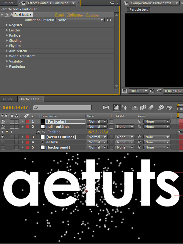
Apply the Particular effect obviously.
Step 9
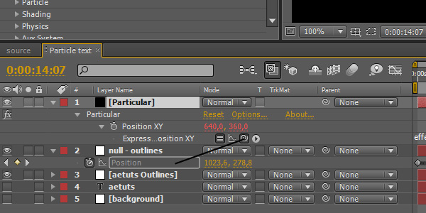
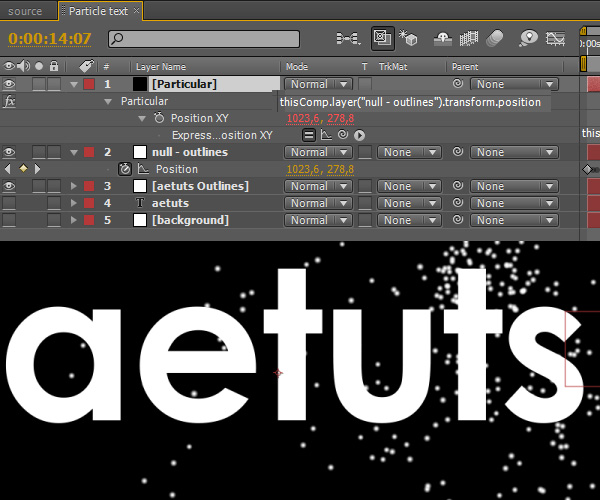
Alt-click on the Position XY property and pickwhip the Position property of our null object.
Step 10
The expression is:
thisComp.layer(“null – outlines”).transform.position
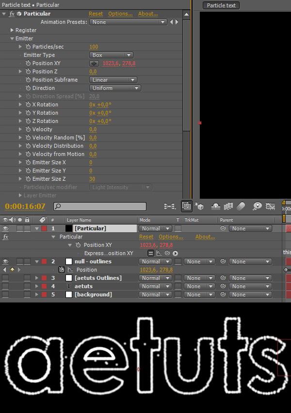
Step 11
Now Particular should follow the outlines of our text layer. Set all Velocity values to 0 to make it stick to the mask path. Also set Emitter Type to “Box”, Emitter Size X and Y to 0 and Emitter Size Z to 30.
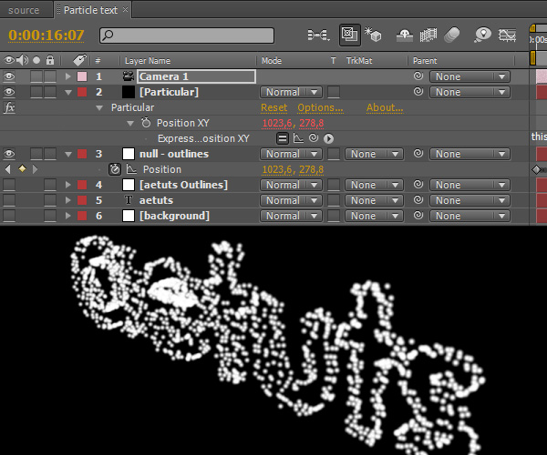
Step 12
Create a new camera, doesn’t matter what settings.
Step 13
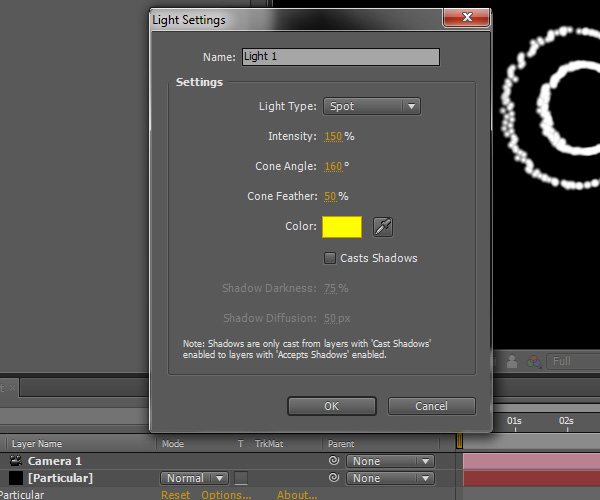
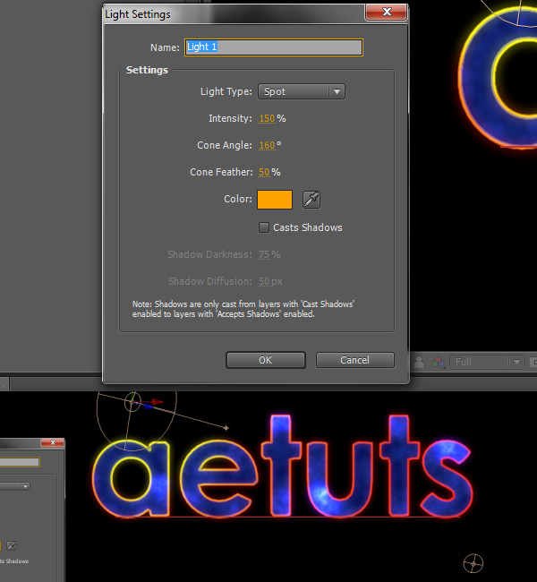
Create a new light, change the Light Type to “Spot”, Intensity to 150%, Cone Angle to 160°, Cone Feather to 50% and make it yellow. Uncheck “Casts Shadows”.
Step 14
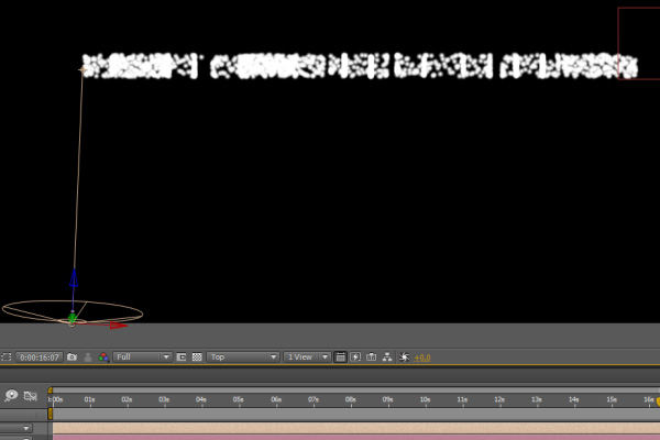
Switch to Top view and position the light as shown on the picture bellow.
Step 15
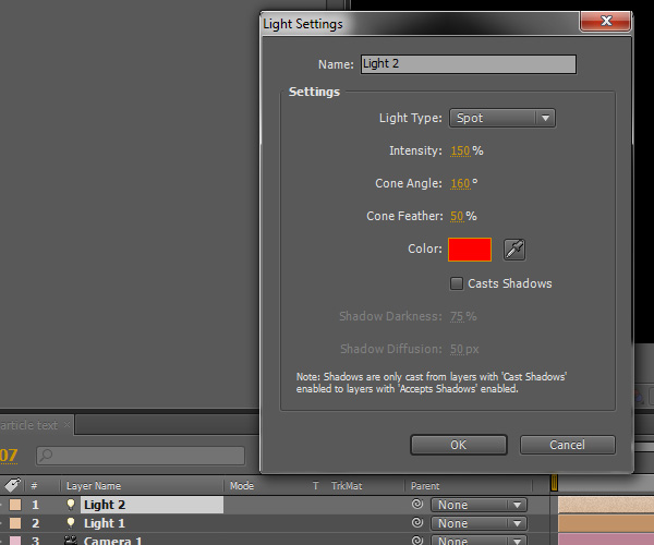
Duplicate the light and position it on the other side of the text.
Step 16
Double click on the duplicated light and change its color to red.
Step 17
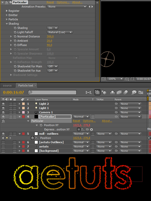
Go to Particular -> Shading and turn it on. Also change the Nominal Distance value to 300 and Diffuse to 90.
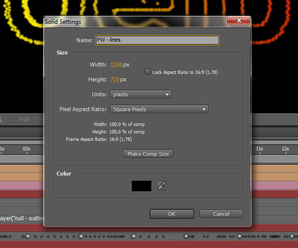
Step 18
Now we will create particles that will kind of reveal our text. Make a new solid and call it “PW – lines” (as in Particle World).
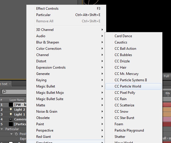
Step 19
Apply the CC Particle World effect.
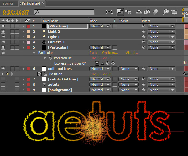
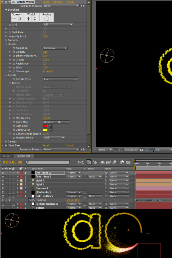
Step 20
Your particle text should look somewhat similar to the picture bellow.
Step 21
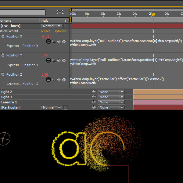
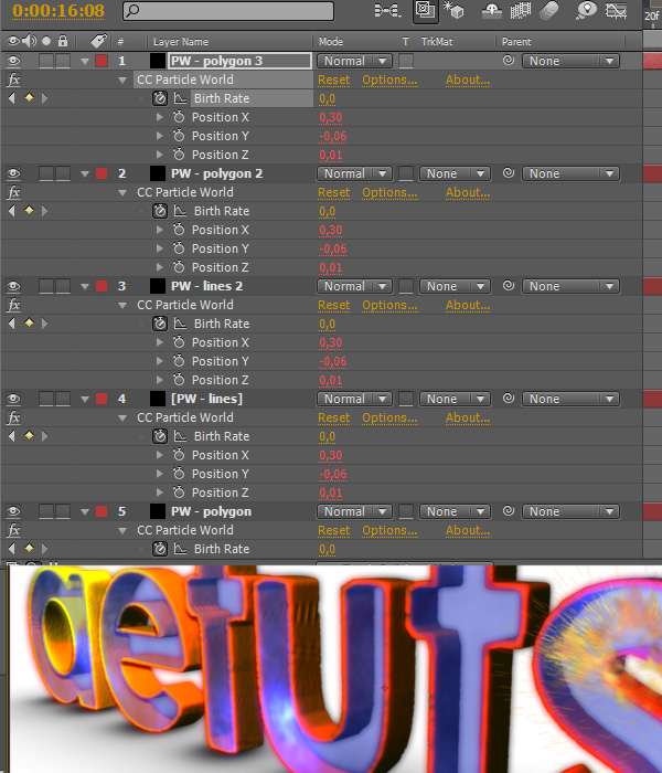
At first we need to make the PW particles follow the path too. Alt-click on Position X and type the following into the expression box:
x=thisCompLayer(“null – outlines”).transform.position[0]-thisComp.width/2;
x/thisComp.width
Alt-click on Position Y and type the following into the expression box:
y=thisCompLayer(“null – outlines”).transform.position[1]-thisComp.height/2;
y/thisComp.width
Alt-click on Position Z and type the following into the expression box:
z=thisCompLayer(“Particular”).effect(“Particular”)(“Position Z”);
z/thisComp.width
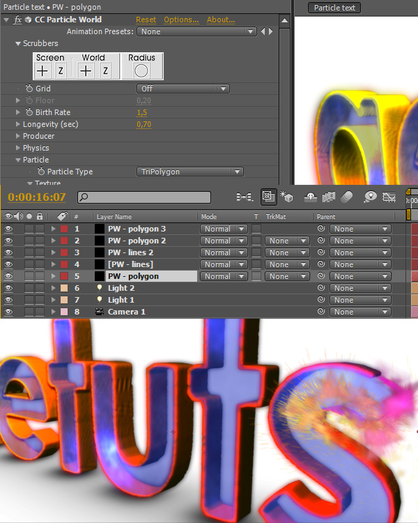
Step 22
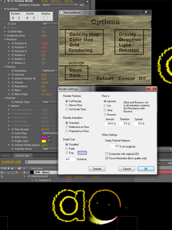
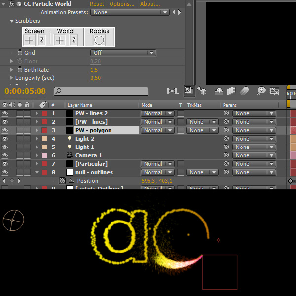
Now let’s change some of the settings.
Turn Grid off obviously.
Set Birth Rate to 1.5.
Set Longetivity to 0.5.
Set Radius X,Y,Z to 0.
Set Velocity to 0.05.
Set Inherit Velocity to 25.
Set Gravity to 0.
Set Max Opacity to 50.
Change the particle Birth and Death colors as shown on the picture bellow.
Set Transfer Mode to Add.
Click on Options->Render Settings and check “Force Motionblur”.
Step 23
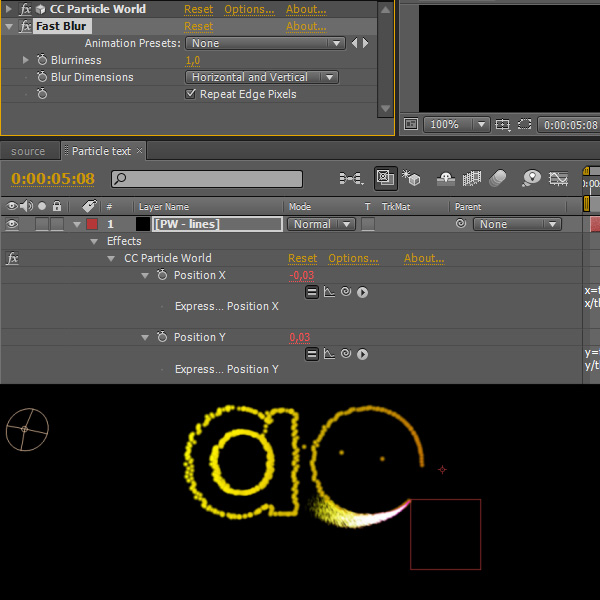
Apply Fast Blur and set Blurriness to 1.
Step 24
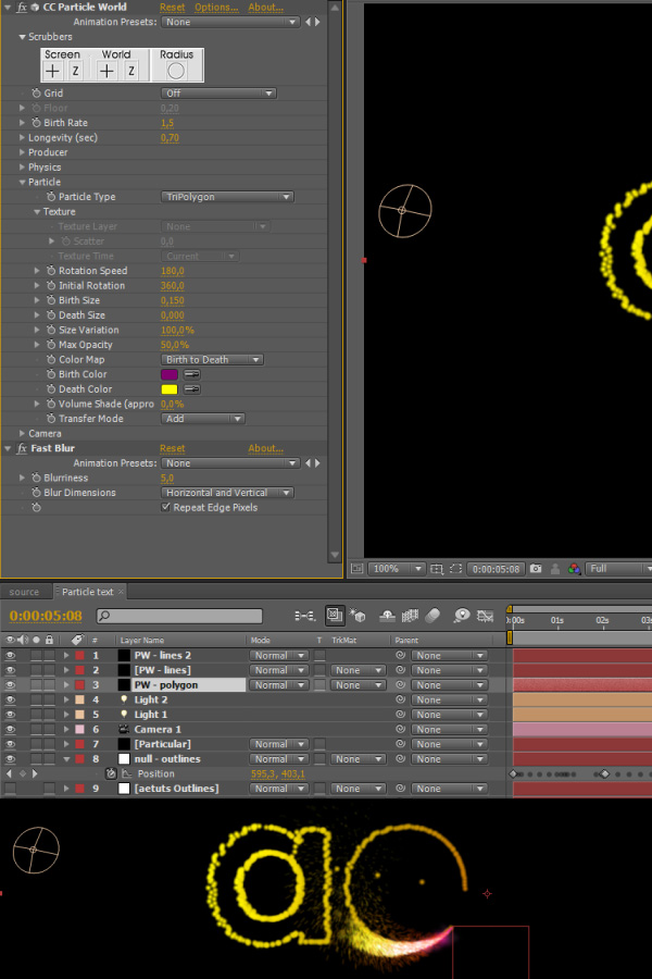
Duplicate the “PW – lines” layer by pressing Ctrl-D and change the values as shown on the picture bellow.
Step 25
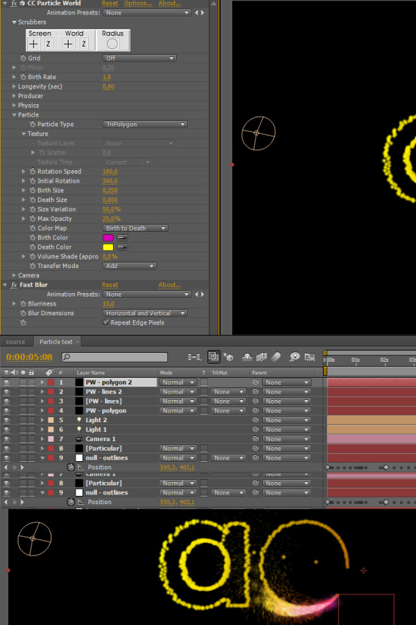
Duplicate the “PW – lines” again, name it “PW – polygon” and put it bellow the original “PW – lines” layer.
Step 26
Change the settings of the “PW – polygon” layer according to the screenshot.
Step 27
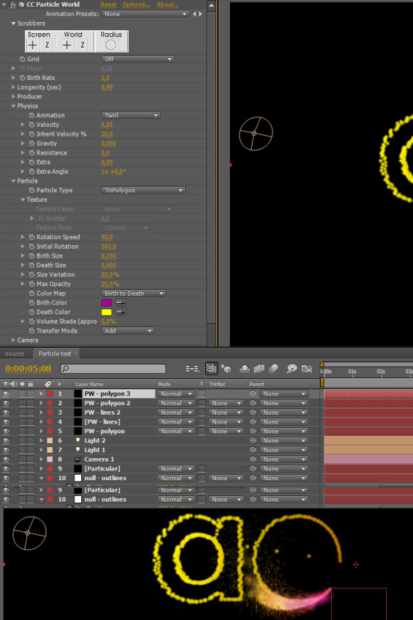
Duplicate the “PW – polygon” layer, put it above all PW layers and change the settings accordingly.
Step 28
And for the last time duplicate the “Pw – polygon 2″ layer and change its settings.
Step 29
Create a new solid layer, make it black and name it “Shadow”.
Step 30
Put it just above the background layer.
Step 31
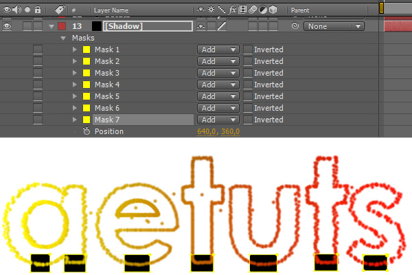
Draw masks as shown on the screenshot bellow. We are basically going to fake some sort of 3D shadow by creating couple of masks around places where normal shadow would appear.
Step 32
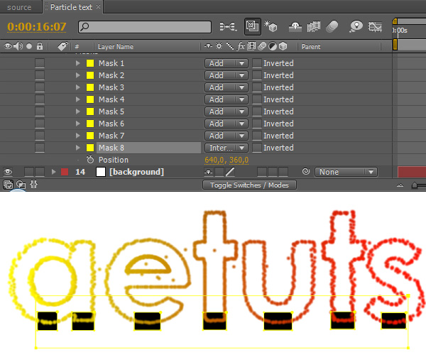
Create another mask that will cover all previous masks.
Step 33
Animate the big last mask so it reveals the smaller shadow masks you’ve created earlier as particular animates and gets closer to them.
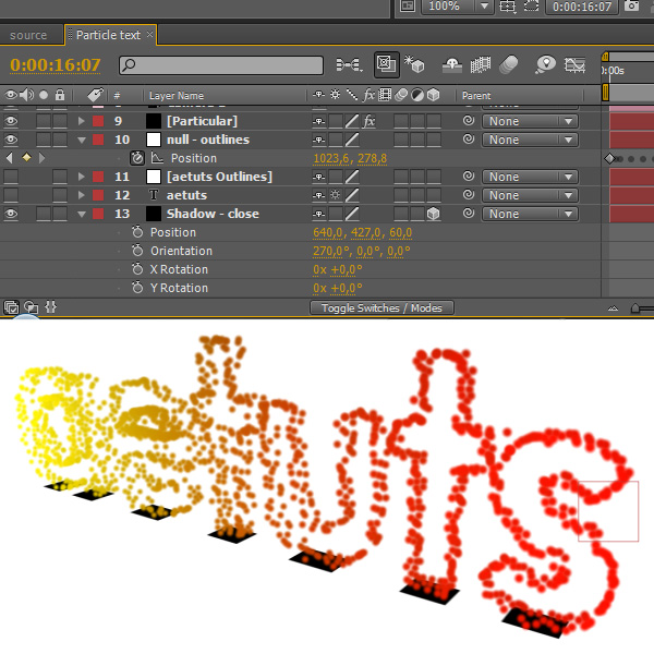
Step 34
Rename the shadow layer to “Shadow – close”, make it 3D, rotate it to 270° on the X axis and change its position to 427px on the Y axis (so it looks like it’s just underneath the text). If you aren’t sure what’s the right value here then just check the Position value of the “null – outlines” layer – you’re looking for the highest value.
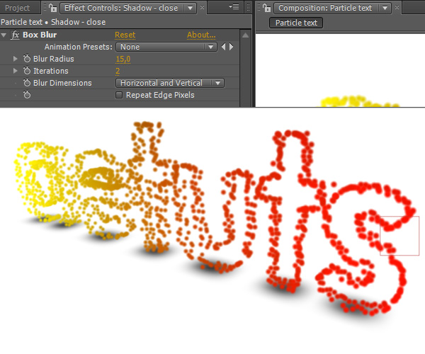
Step 35
Apply the Box Blur effect, set Blur Radius to 15 and Iterations to 2.
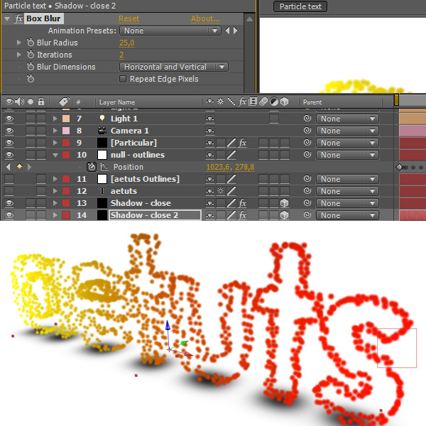
Step 36
Duplicate the “Shadow – close” layer and change its settings.
Step 37
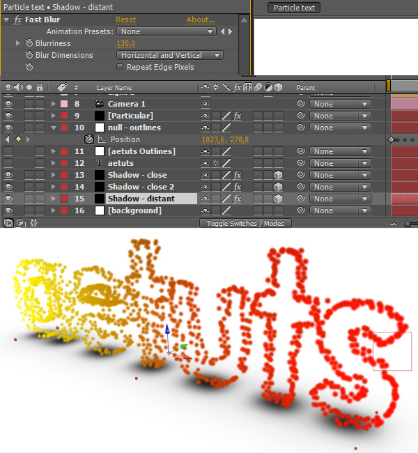
Duplicate it again, change its name to “Shadow – distant”, delete the Box Blur effect, apply Fast Blur and set Blurriness to 130.
Step 38
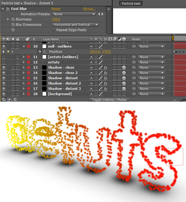
Duplicate the “Shadow – distant” layer twice and change Blurriness to 150.
Step 39
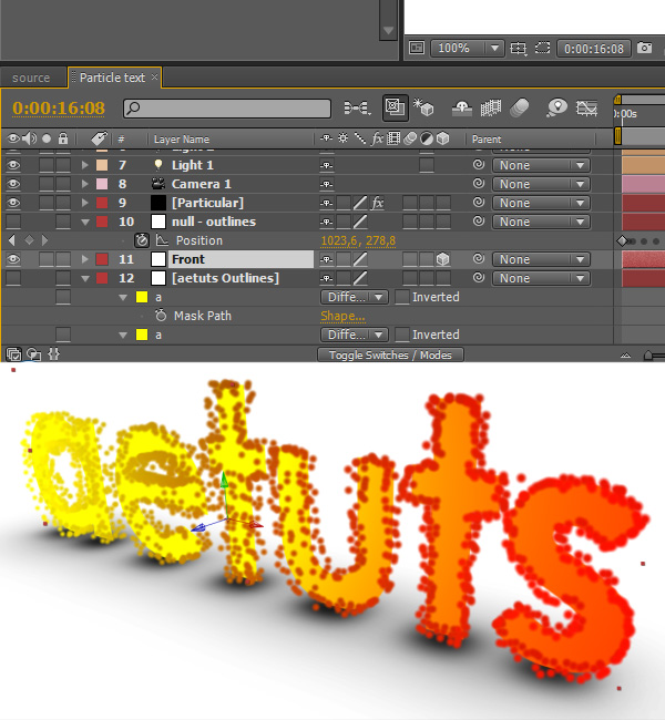
Duplicate the “aetuts Outlines” layer, make it 3D and rename it as “Front”.
Step 40
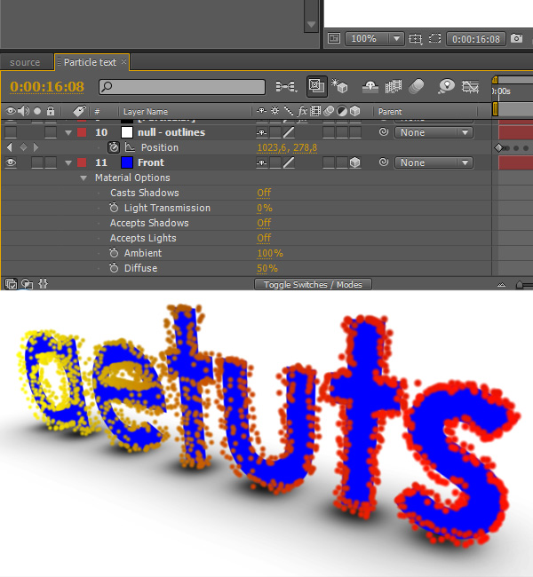
Go to Material Options (press AA) and turn Accepts Shadows and Accepts Lights Off. Also change the layer color to blue.
Step 41
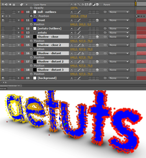
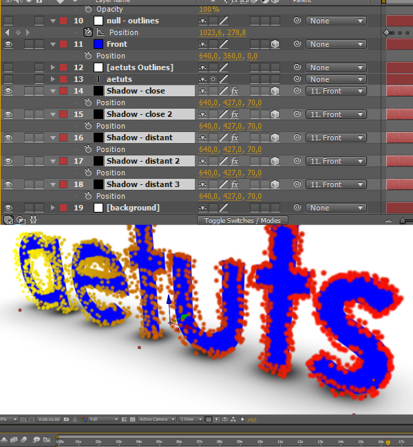
Select all shadow layers, press P and set their Z-position to 70.
Step 42
Parent all shadow layers to the Front layer.
Step 43
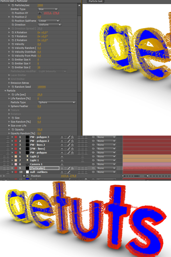
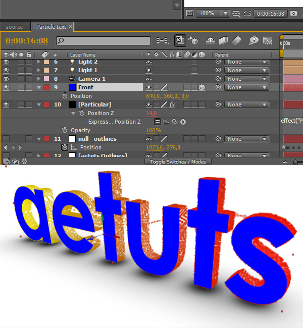
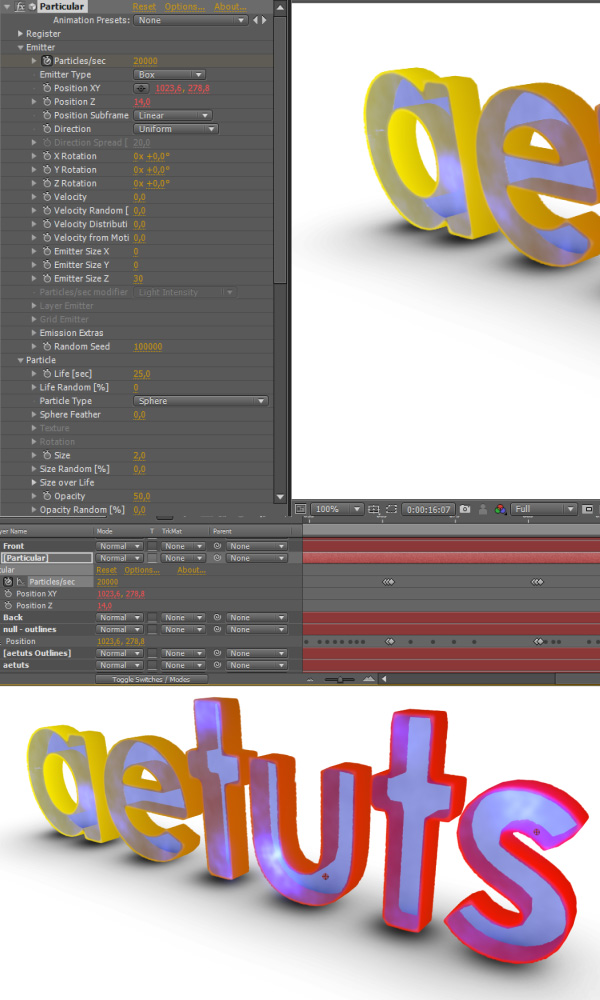
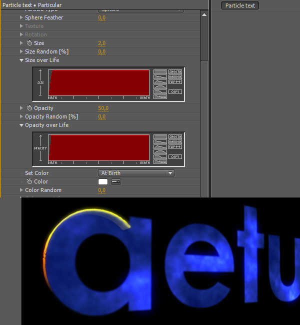
Now let’s change Particular’s settings to make it look a bit better. Set Particles/sec to 2000, Life to 25, Sphere Feather to 0, Size to 2 and Opacity to 50.
Step 44
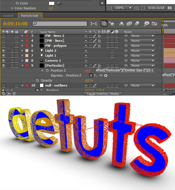
Alt-click on Position Z and type the following:
effect(“Particular”)(“Emitter Size Z”)/2-1
This way we tell Particular to push the particles back in the Z-space so they line up nicely with the Front layer.
Step 45
Put the Front layer above the Particular one.
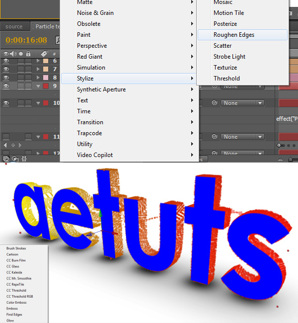
Step 46
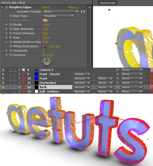
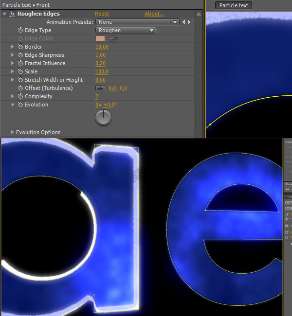
Apply the Roughen Edges to the Front layer.
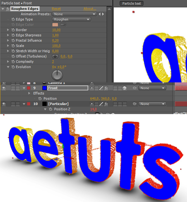
Step 47
Change the settings as shown on the picture bellow to roughen the edges a bit.
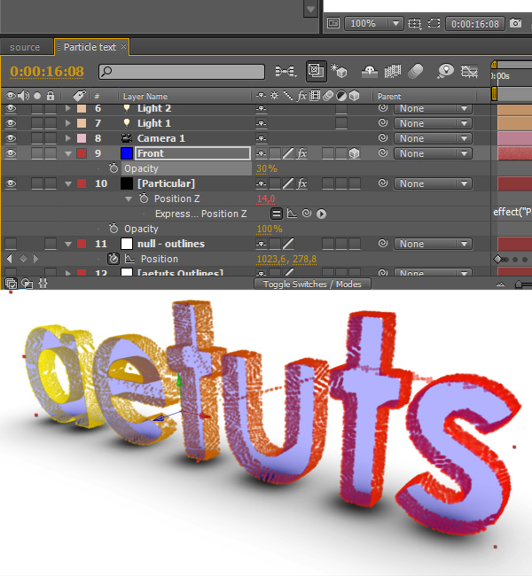
Step 48
Set Opacity of the Fron layer to 30%.
Step 49
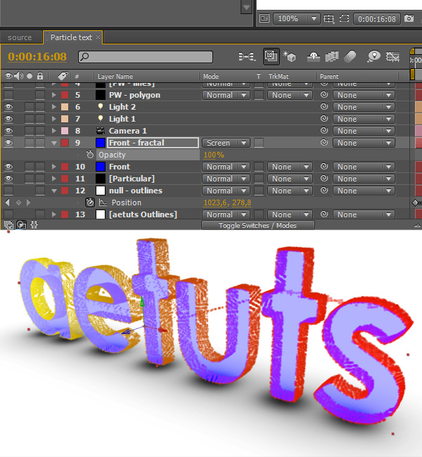
Duplicate the Front layer, name it “Front – fractal” and set the Transfer Mode to Screen.
Step 50
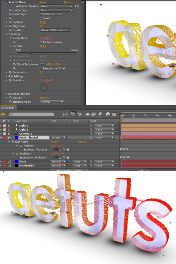
Apply the Fractal Noise effect and change its settings as shown on the screenshot. It kind of doesn’t matter what values you use, just make it animate so the front layer doesn’t look static. Also change the transfer mode to “Screen”.
Step 51
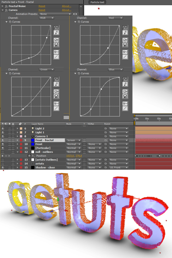
Apply the Curves effect to the Front – fractal layer and play around with the values.
Step 52
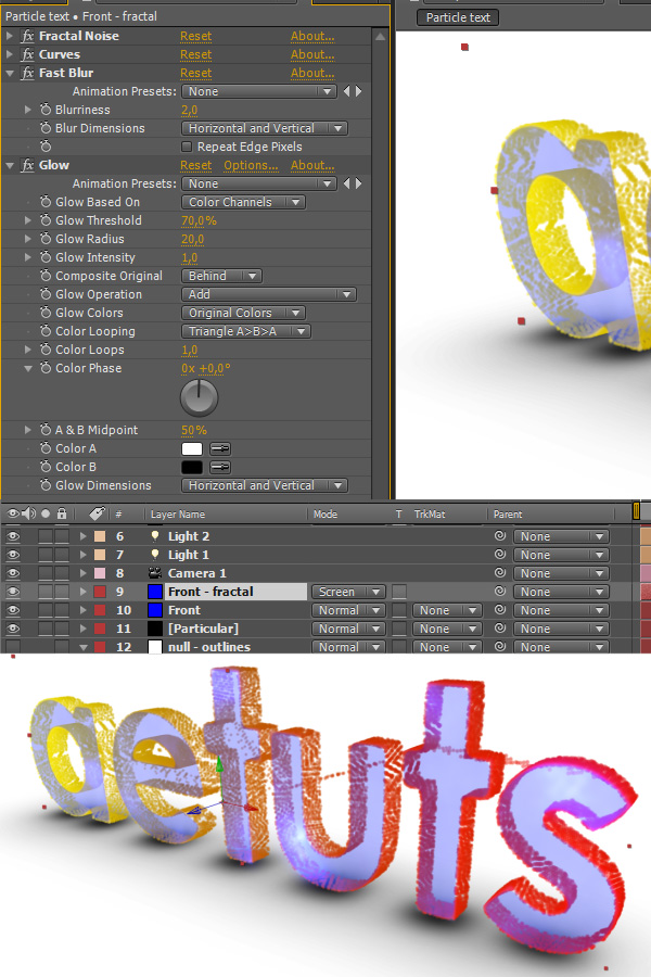
Apply the Fast Blur effect and set Blurriness to 2. Apply the Glow effect and set Glow Threshold to 70.
Step 53
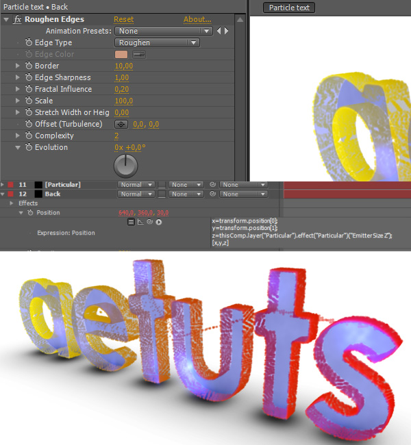
Duplicate the Front layer, name it Back and make it black. And put it bellow the Particular layer.
Step 54
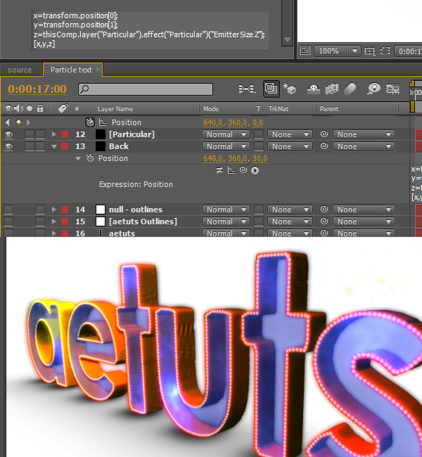
As the layer name suggests, this will be our back layer. Alt-click on Position and type the following:
x=transform.position[0];
y=transform.position[1];
z=thisComp.layer(“Particular”).effect(“Particular”)(“Emitter Size Z”);
[x,y,z]
This way the back layer will be positioned at the end of the particles (talking about the Z-space).
Step 55
At this point we will get rid of those annoying lines that appear when Particular is skipping from one letter to another. Select null – outlines and press P, it will help you place new keyframes for Particular. Make a keyframe for Particles/sec one frame before the end of current letter and set it to 20000. Move one frame forward (which is the last keyframe of current letter) and set Particles/sec to 0. Move one frame forward yet again (which is the very first keyframe of the next letter) and set Particles/sec to 20000. Basically we are just trying to set Particles/sec to 0 every time Particular “skips” onto the next letter.
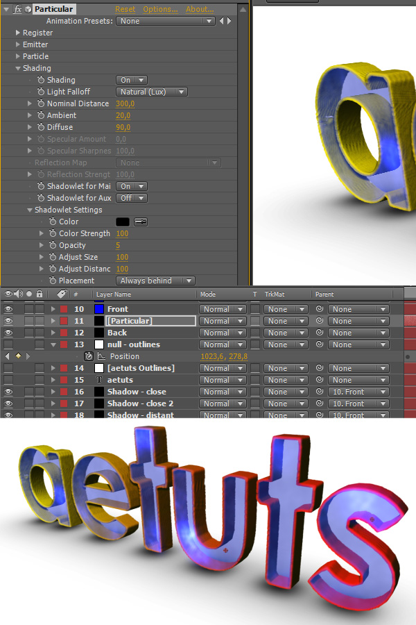
Step 56
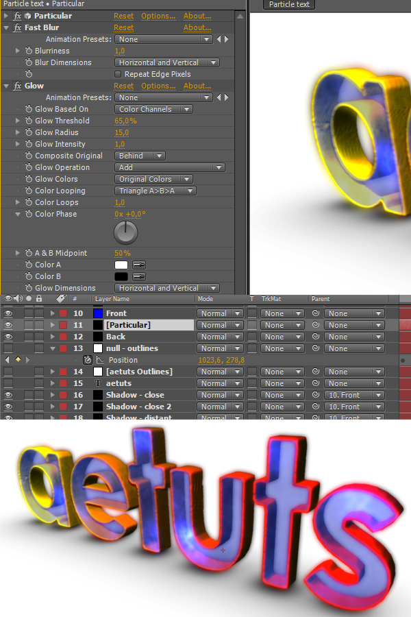
In Particular->Shading turn Shadowlet for Main particles on and set Placement to “Always behind”.
Step 57
Apply Fast Blur to the Particular layer and set Blurriness to 1. Also apply the Glow effect and set Glow Threshold to 65% and Glow Radius to 15.
Step 58
Feel free to adjust light’s position …
Step 59
… and other properties.
Step 60
And the same for the second light.
Step 61
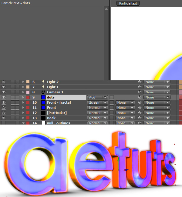
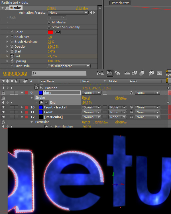
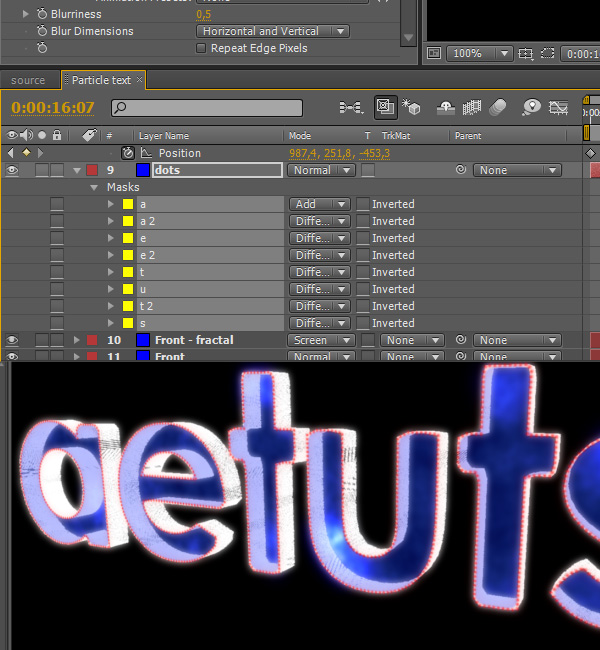
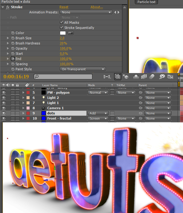
Duplicate the “Front – fractal” layer, name it “dots”, change transfer mode to Add and delete all effects.
Step 62
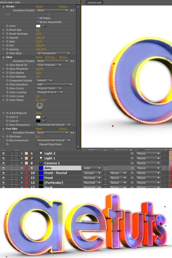
Apply the Stroke, Glow and Fast Blur effects and change their settings as shown on the screenshot bellow.
Step 63
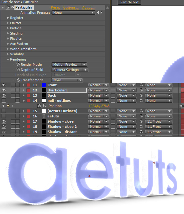
Go to Particular->Rendering and set Render Mode to “Motion Preview”. This is just temporary so the scene gets rendered faster.
Step 64
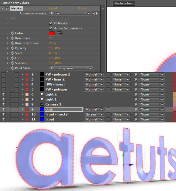
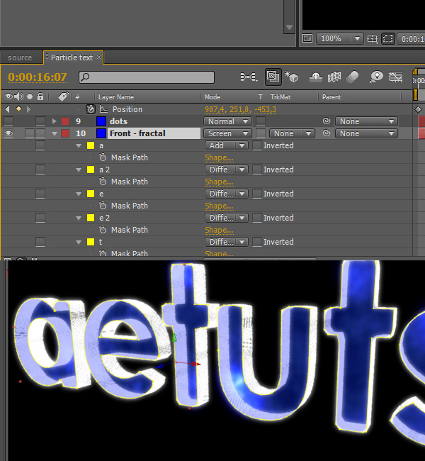
Go to dots and change the stroke color to red so we can see the dots better.
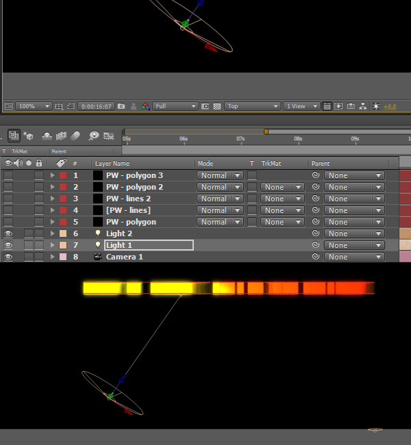
Step 65
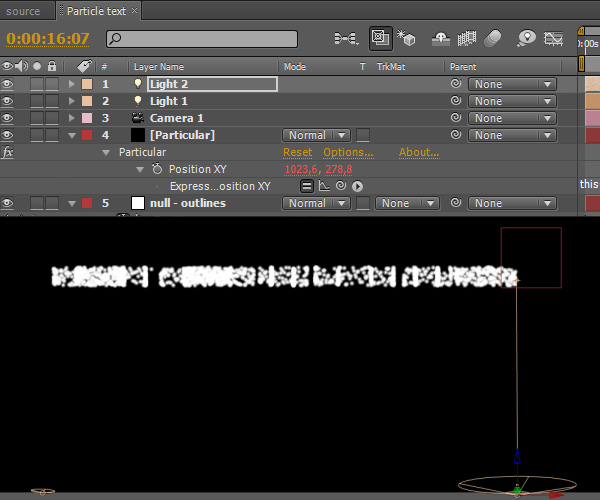
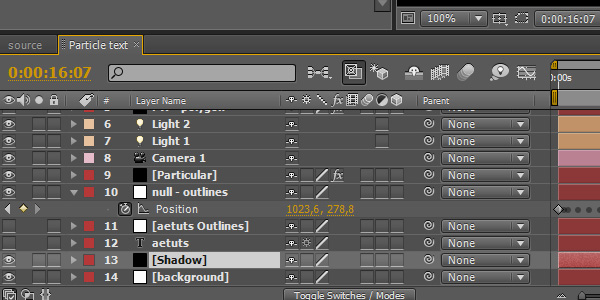
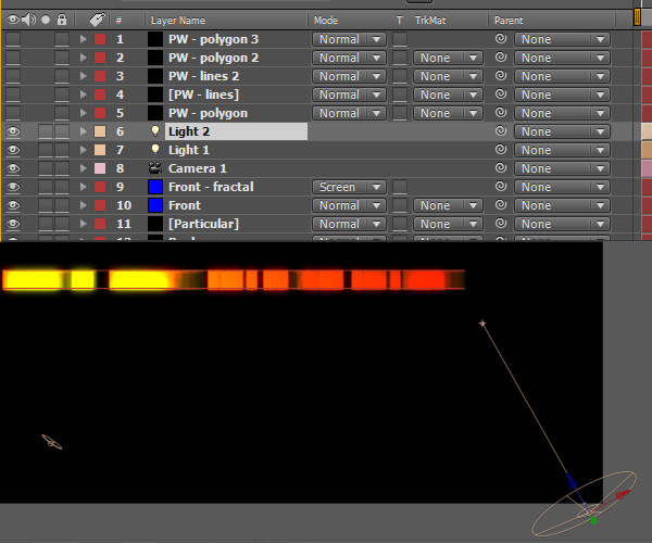
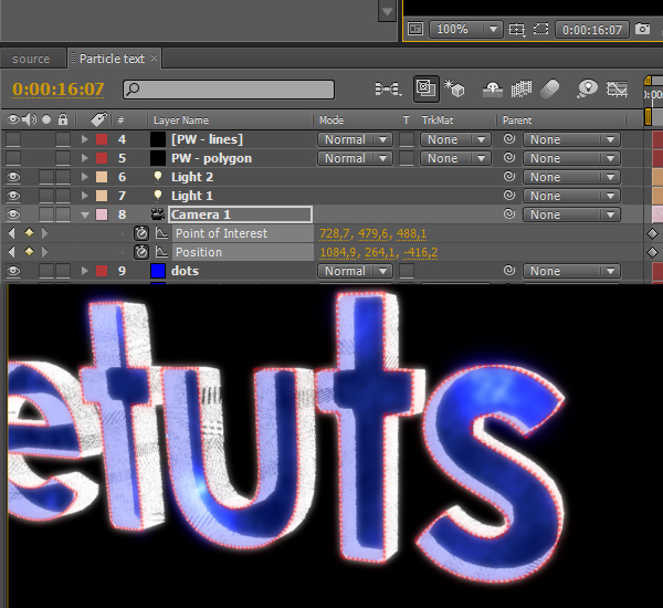
But let’s animate the camera first. In my case the camera movement ends at 16:07 with the values shown on the screenshot. At this point I also temporarily disabled background.
Step 66
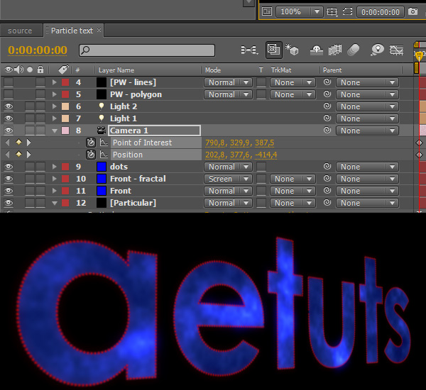
And obviously change the camera settings at the beginning too.
Step 67
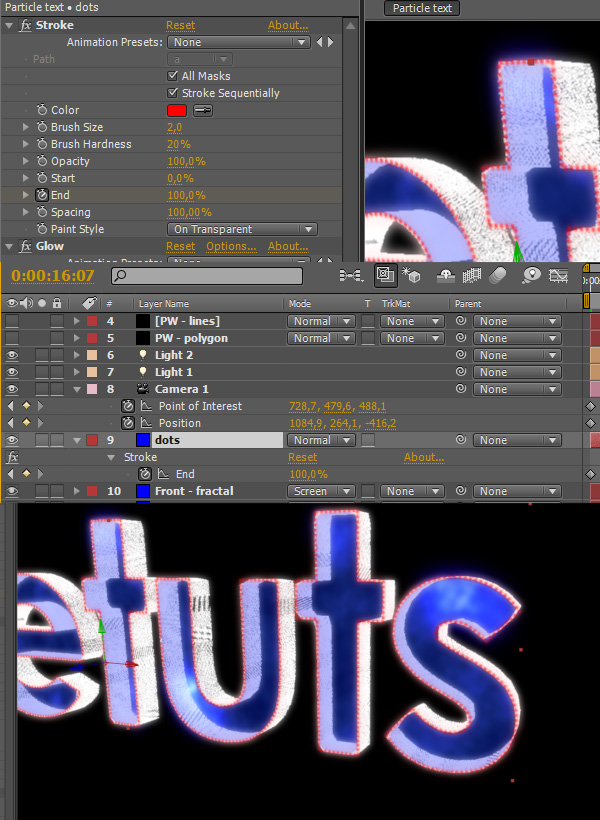
Go to 16:07 and set a keyframe for the End property and make it 100%.
Step 68
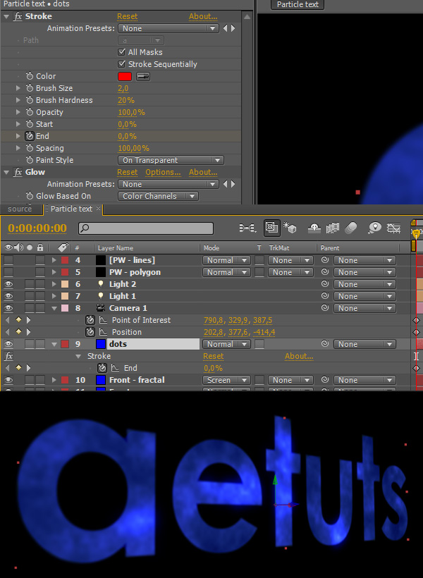
Go to the beginning of the composition and set End to 0%.
Step 69
Now you are going to have quite a lot of keyframes to make sure that the dots follow the particles. It doesn’t matter if the dots are slighly lagging behind the particles, but make sure they are in no case ahead.
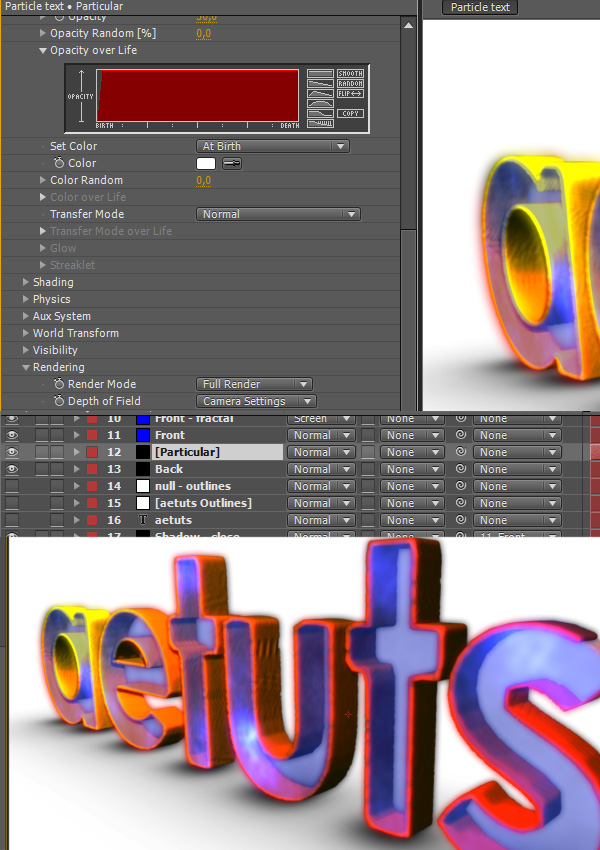
Step 70
Go to Particular and change Size over Life and Opacity over Life as shown on the screenshot bellow. At this point I also temporarily switched back to Full Render mode to see how the particles get rendered.
Step 71
Now (back in Motion Preview mode) when you click on the Front layer you can see that the particles actually don’t follow the original mask path. There are two ways of fixing this. You can either make the composition last longer (like 40 seconds, assuming that you would make all layers last longer too) thus giving Particular more time to render the particles or you can just adjust the masks so they match the particles. And that’s exactly what we are about to do.
Step 72
Just adjust the mask points, it’s no big deal.
Step 73
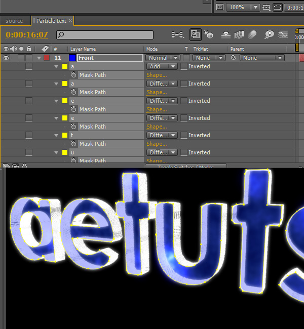
Select all mask paths of the Front layer and copy them (Ctrl-C).
Step 74
Select the Front – fractal layer, delete the current masks and paste the fixed ones.
Step 75
Do the same for the dots layer.
Step 76
Go to Particular and change the Render Mode back to Full Render so we can see the result so far. Also enable the background layer.
Step 77
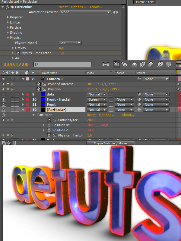
Go to 17:00 (that’s where I want my animation to end) and set a keyframe for Physics Time Factor.
Step 78
Move one frame forward and set it to 0.
Step 79
Select all CC Particular World layers and enable them.
Step 80
With all PW layers selected and at 16:07 set a keyframe for Birth Rate. Move one frame forward and set them to 0 so the particles stop emitting.
Step 81
Enable the dots layer and change the color to white.
Step 82
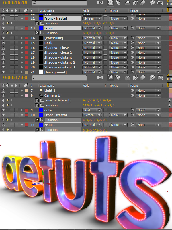
Go to 16:18 and set keyframes for the Position property of the Front and Front – fractal layers. Set them to -1000 (the Z value) . Go to 17:00 and set them back to 0.
Step 83
Disable the expression for the position of the Back layer.
Step 84
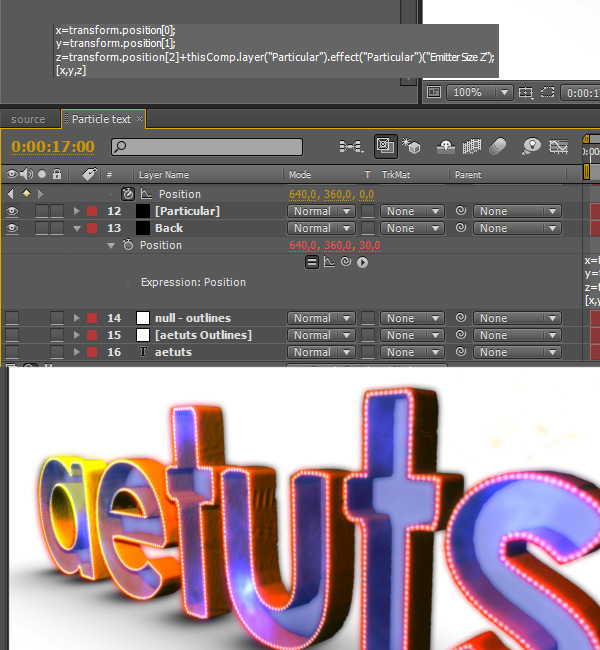
We have to change the expression so we can actually make the layer animate. The x and y variables stay the same, the only difference in in the z variable. Updated expression:
x=transform.position[0];
y=transform.position[1];
z=transform.position[2]+thisComp.Layer(“Particular”).effect(“Particular”)(“Emitter Size Z”);
[x,y,z]
This way the Z value is computed from its actual value + the Emitter Size Z value.
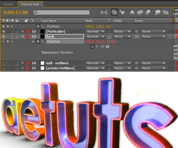
Step 85
At 17:00 push the Back layer all the way back and don’t forget to make a keyframe.
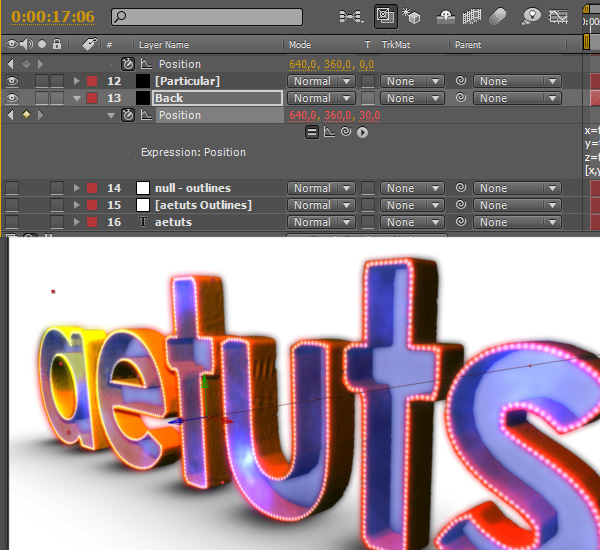
Step 86
At 17:06 set the Z-position back to 30.
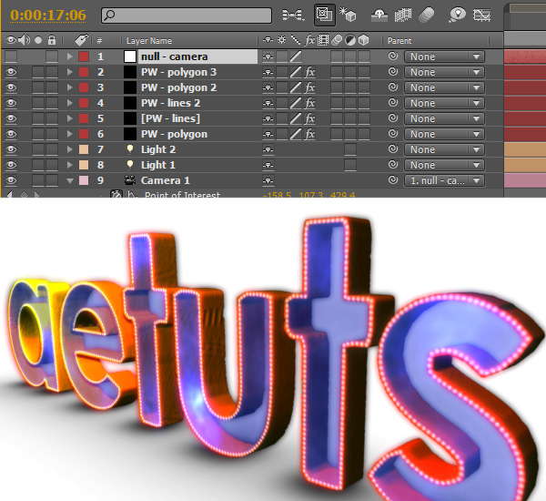
Step 87
Create a new null object and name it “null – camera”. Also parent the camera to this null. We will use it to control our camera shake effect.
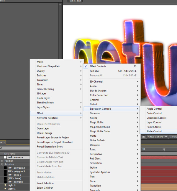
Step 88
Apply Slider Control three times.
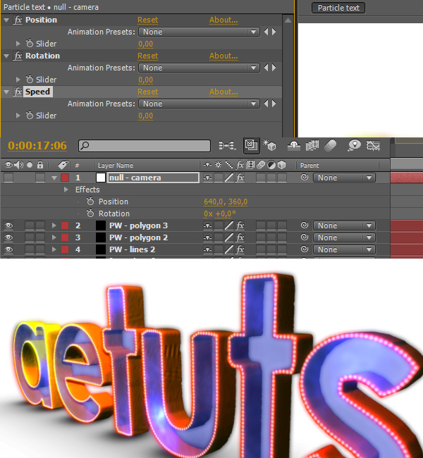
Step 89
Rename them as Position, Rotation and Speed.
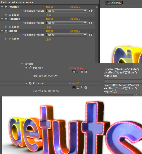
Step 90
Select the null – camera layer, hit P, Alt-click on Position and type the following:
p = effect(“Position”)(“Slider”);
s = effect(“Speed”)(“Slider”);
wiggle(s,p);
Hit R, Alt-click on Rotation and type the following:
r = effect(“Rotation”)(“Slider”);
s = effect(“Speed”)(“Slider”);
wiggle(s,r);
This way we can control the position and rotation value via the sliders.
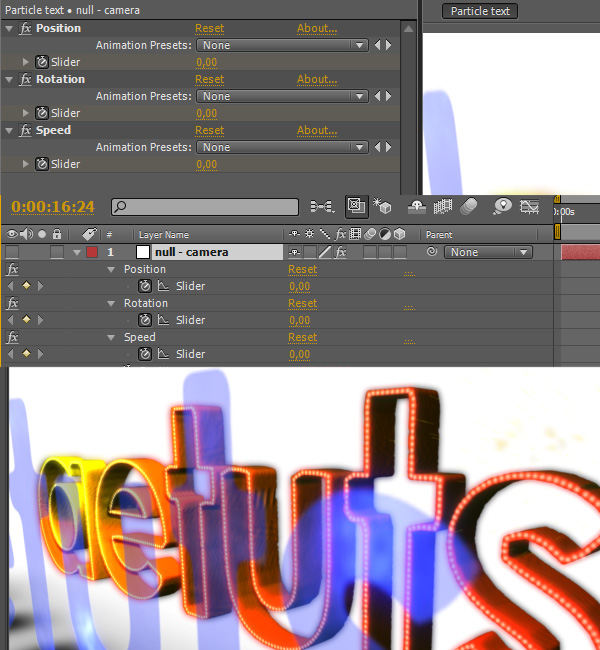
Step 91
At 16:24 (when the front layers are about to hit the particles) set all sliders to 0.
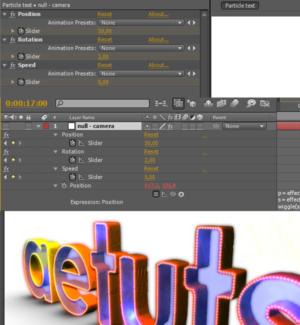
Step 92
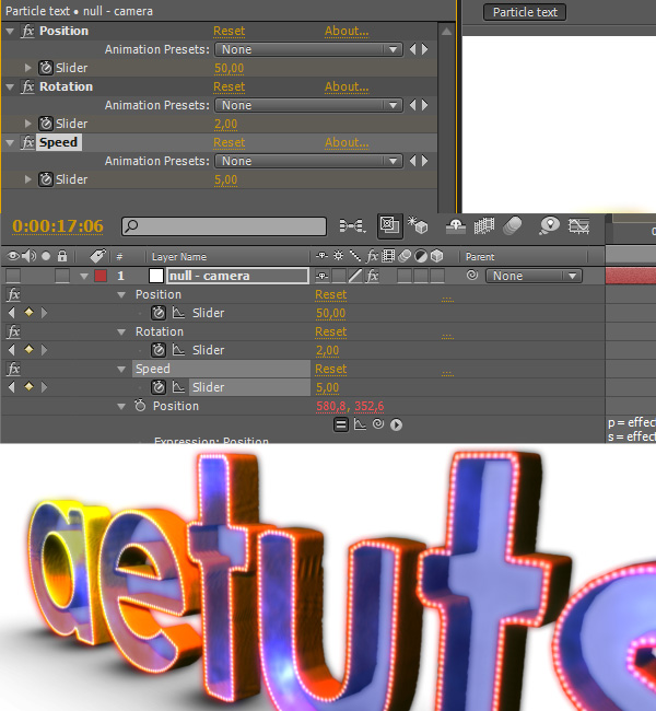
Move one frame forward and set the Position slider to 50, the Rotation slider to 2 and the Speed slider to 5.
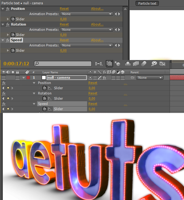
Step 93
Go to 17:12 (we want our shake effect to last for 12 frames) and set the sliders to 0.
Step 94
But the thing is that we want to have two shake effects (one for the front layers, one for the back layer). But we are using only one camera controller so we need to set three keyframes at 17:05 (one frame before the impact of the back layer) to kind of let the original shake effect fade out. Also don’t forget to delete the three keyframes with 0 value placed at 17:12 – we won’t need them anymore.
Step 95
At 17:06 reset the slider values back to 50, 2 and 5.
Step 96
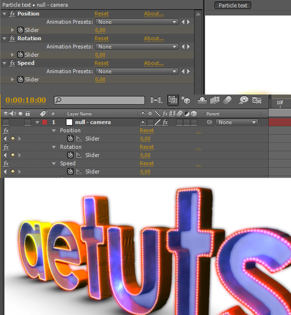
Go to 18:00 and set all sliders to 0.
Step 97
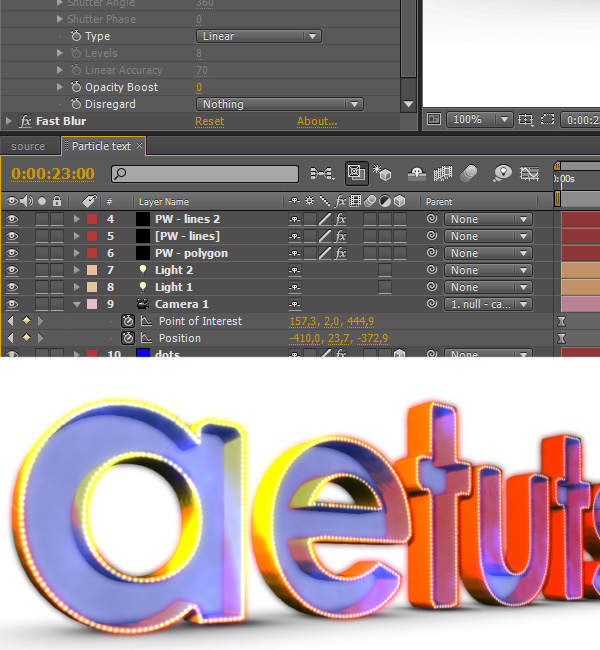
Go to 23:00. We will animate the camera once again and make it come back to the beginning of our particle text. Also select all camera keyframes and press F9 to apply Easy ease.
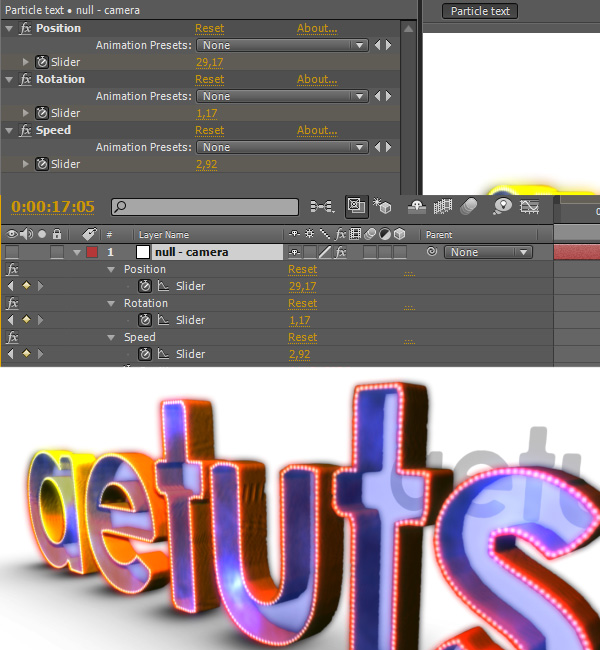
Step 98
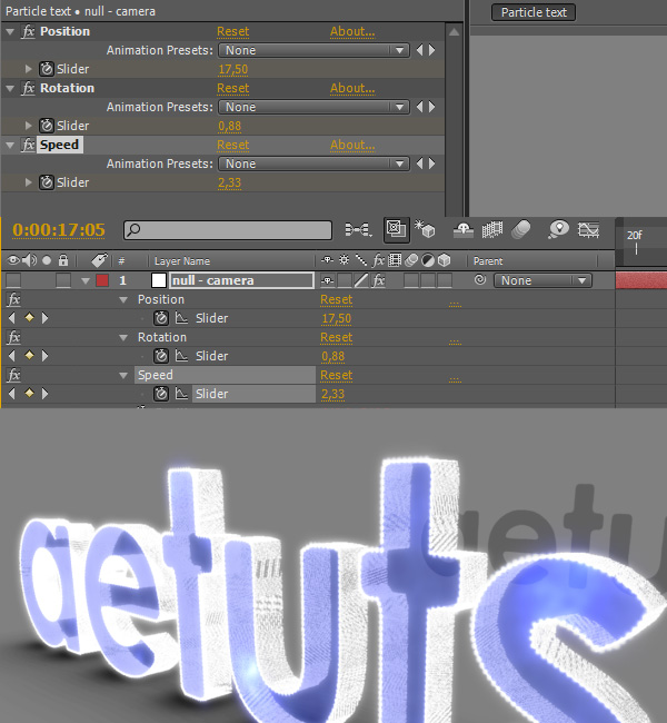
At this point I decided to tweak the shake values a bit, so at 17:05 I changed them to the ones shown on the screenshot bellow.
Step 99
Delete all layers that aren’t used and turn on Motion Blur for desired layers.
Additional Aetuts+ Resources