
This tutorial will show you how to use Photoshop’s 3D tools and settings, with some adjustment layers, to create a 3D paper text effect. Let’s get started!
This text effect was inspired by the many Layer Styles available on GraphicRiver.
Tutorial Assets
The following assets were used during the production of this tutorial:
- Built Titling font
- Smooth_stucco_flat_white_paint_plaster_wall_textur by hhh316
1. How to Create Text Shape Layers
Step 1
Create a new 1250 x 800 px document.
Then, create the text in All Caps using the font Built Titling Bold. Set the Size to 300 pt, and the Tracking to 100.

Step 2
Rename the text layer to Text, and then right-click it and choose Convert to Shape.

Step 3
Duplicate the Text layer twice, and then rename the first copy to Bottom and the second to Top.

2. How to Subtract Shapes
Step 1
Drag a Guide where you want to separate the text to bend it in the 3D effect.

Step 2
Pick the Rectangle Tool, make sure that the Top layer is selected, and then hold the Option key to subtract shapes.
Click-drag to create a rectangle that covers the lower part of the text, starting from the guide you added. You can release the Option key and use the Space Bar to move the rectangle if needed.

Step 3
Once you create the rectangle, the bottom part will be removed.
To clean up the path, click the Path operations icon in the Options bar, and then choose the Merge Shape Components option.

Step 4
Repeat the same steps to the Bottom layer, subtracting the upper part this time.

3. How to Create 3D Background Layers
Step 1
With the Rectangle Tool still selected, create a new rectangle shape that extends quite a bit outside the document’s edges, and call its layer Background.

Step 2
Duplicate the Background layer, and then select both the Rectangle copy and Text layers.

Step 3
Go to Layer > Combine Shapes > Subtract Shapes at Overlap. This will subtract the text from the rectangle background shape.

4. How to Convert Shape Layers Into 3D Layers
Step 1
For each shape layer you have, select it, and then go to 3D > New 3D Extrusion from Selected Path.

Step 2
Select all the 3D layers, and then go to 3D > Merge 3D Layers.

5. How to Work With the 3D Scene
Step 1
To access the 3D mesh settings and properties, you’ll need to open two panels: the 3D panel and the Properties panel (both found under the Window menu).
The 3D panel has all the components of the 3D scene, and when you click the name of any of those, you’ll be able to access its settings in the Properties panel. So make sure to always select the tab of the element you want to modify in the 3D panel before you change its settings in the Properties panel.

Step 2
If you select the Move Tool, you’ll find a set of 3D Modes for it to the right of the Options bar.
When you choose one of those, you can then click and drag to perform changes (on the selected element in the 3D panel).

6. How to Modify the 3D Mesh Settings
Step 1
Select the Top, Bottom, and Background mesh tabs in the 3D panel, and then, in the Properties panels, change the Extrusion Depth to 2 px.

Step 2
Select the Text mesh tab, and then change its Extrusion Depth to 5 px.

Step 3
Select all the mesh tabs, and then click the Coordinates icon at the top of the Properties panel, and change the X Rotation Angle to 90.

Step 4
Click the 3D panel menu icon, and choose Move Object to Ground Plane.
If you still can’t see all the 3D meshes, you can go to 3D > Pack Objects on Ground Plane, or select each mesh and move it to the Ground Plane separately.

7. How to Reposition the 3D Meshes
Step 1
Pick the Move Tool, and use the 3D Axis to move the 3D meshes in the scene.
The arrows at the ends of the axis move the mesh, the part below them is used for rotation, and the cubes are used for scaling. The cube in the center is used to scale the object uniformly. All you need to do is click and drag the part you want.

Step 2
You can also click the Current View tab, and then choose any of the View dropdown menu options in the Properties panel, to help you better place the meshes.

Step 3
Keep in mind that you can use the Move Tool‘s 3D Modes to adjust the view.

Step 4
Keep a slight distance between the Background and Text meshes to create some space.
It might take a while and a lot of going back and forth between the different views, but you should end up with a result like the one below.
You can always make any adjustment whenever needed, especially after applying the materials and adjusting the lighting.

8. How to Create an Illuminating Background Material
Step 1
Select all the Material tabs you have, and then click the Diffuse texture icon and choose Remove Texture.

Step 2
Select the Background Front Inflation Material tab, and use these settings:
(The color values used are in RGB.)
- Diffuse: 197, 163, 163
- Specular: 239, 226, 231
- Illumination: 145, 76, 84
- Shine: 50
- Reflection: 10

9. How to Create a Background Using Two Materials
Step 1
Select the Text Front Inflation Material tab, and use these settings:
- Diffuse: 231, 228, 228
- Specular: 239, 235, 230
- Illumination: 35, 34, 32
- Shine: 50

Step 2
Click the Bump folder icon and choose Load Texture, and then open the Smooth_stucco_flat_white_paint_plaster_wall_textur image.

Step 3
Click the Bump texture icon and choose Edit UV Properties.

Step 4
Adjust the Tile and Offset values until you like the effect.

Step 5
Decrease the Bump value to 3.

Step 6
Select the Text Front Bevel, Text Extrusion, and Text Back Bevel Material tabs, and use these settings:
- Diffuse: 197, 163, 163
- Specular: 239, 226, 231
- Illumination: 145, 76, 84
- Shine: 50
- Reflection: 10

10. How to Create a 3D Paper Material
Step 1
Select the Bottom Front Inflation Material tab, and use these settings:
- Diffuse: 231, 228, 228
- Specular: 239, 235, 230
- Illumination: 35, 34, 32
- Shine: 50
Use the same Bump texture.

Step 2
Adjust the UV Properties values as needed.

Step 3
Click the Material Picker box, and then click the pop-up menu icon, and choose New Material.

Step 4
Type in a name for the material, and click OK.

Step 5
Select the rest of the Top and Bottom Material tabs.
Open the Material Picker, scroll down to the material icon you’ve just saved, and click it to apply it to the selected materials.

11. How to Adjust a 3D Scene’s Lighting
Step 1
Click the Infinite Light 1 tab in the 3D panel, and then, in the Properties panel, change the Type to Spot.
Use these settings for the Spot Light:
- Intensity: 65
- Shadow Softness: 30
- Hotspot: 10
- Cone: 25
- Check the Light Falloff box
- Inner: 1000
- Outer: 3000
You can also use any other values you prefer.

Step 2
Use the Move Tool, or the Coordinates values, to reposition the Spot Light until you get a lighting that you like.

Step 3
Click the Environment tab, and change the Intensity to 25%.
Once you’re done, make sure that all the meshes are well placed, and choose a final camera view for the scene.

12. How to Create a Depth-of-Field Effect
Step 1
Select the Scene tab, and then choose the Hidden Wireframe option from the Presets dropdown menu.
This will help you better see the out-of-focus effect.

Step 2
Select the Current View tab, and change the Depth of Field Depth value to 8.
Depending on the camera angle you have, you might need to use different Distance and Depth values. The Hidden Wireframes view will help you see the results as you change the values.

Step 3
Go back to the Scene tab, and set it back to Default.

Step 4
If there’s nothing else you want to change, go ahead and render the scene by going to 3D > Render 3D Layer.
The rendering might take a while, but you can stop it any time by pressing the Esc key.

13. How to Adjust the Rendered Scene
Step 1
Click the Create new fill or adjustment layer icon at the bottom of the Layers panel and choose Selective Color.

Step 2
Choose Reds and use these settings:
- Cyan: -35
- Magenta: 30
- Yellow: 10
- Black: 5

Step 3
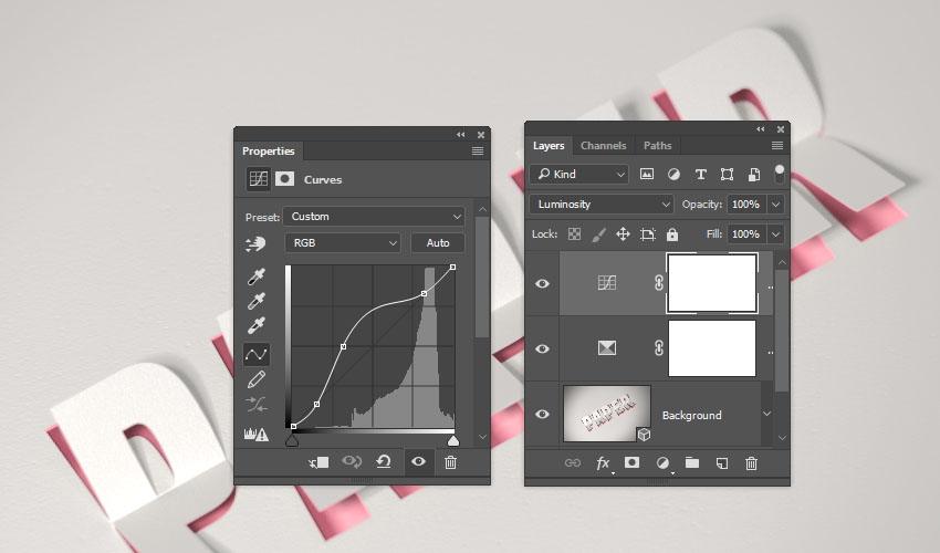
Add a Curves adjustment layer, change its Blend Mode to Luminosity, and make a curve that creates a final effect you like.
Congratulations, You’re Done!
In this tutorial, we created text and background shape layers to use for the effect. Then, we converted the shape layers into 3D layers and adjusted their mesh settings.
After that, we repositioned the meshes, created the different materials, adjusted the lighting, added a depth of field effect, and rendered the 3D scene.
Finally, we used adjustment layers to finish off the effect.
Please feel free to leave your comments, suggestions, and outcomes below.

{excerpt}
Read More