Creating metallic objects can be a challenge, so here’s a tutorial that will show all the techniques you will need to create the elements of a 3D metallic object. You will learn helpful skills in rendering metallic effects, how to draw objects in 3D and some great tips on working with the Gradient Mesh. Let’s begin!
Step 1
To begin you need to create the main geometry sketch of the mincing machine which is shown in the diagram below.
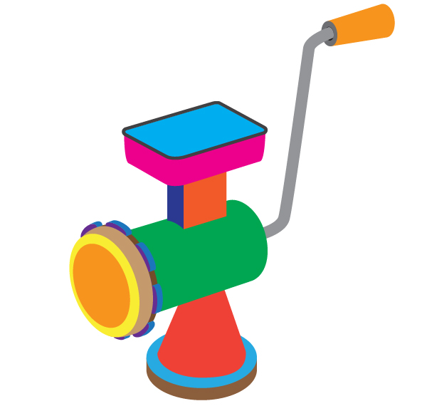
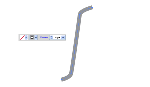
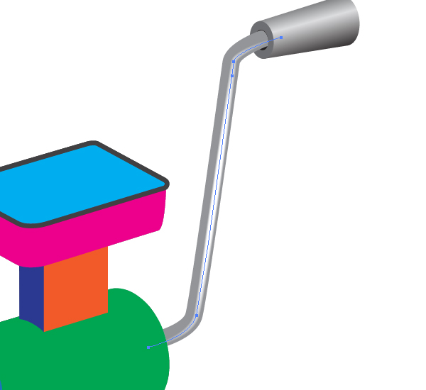
This sketch is flat because it has no the light distribution, but you should create it so you can plan the final image. If you know how to achieve the main outlines of the object and its elements, go to the Step 11. If not, read the following steps carefully. Take the Pen Tool (P), change the Stroke color to gray and the filling color to None, and illustrate the path which will represent the machine handle.
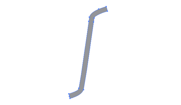
Go to Object > Expand, then go to Object > Ungroup.
Step 2
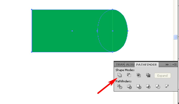
Take the Rectangle Tool (M) and produce the shown path.

Then take the Ellipse Tool (L) and draw an ellipse at the right end of the rectangle.

Select both green paths and click the Unite button in the Pathfinder palette. Or if you use the fifth (or the sixth) CS version of Adobe Illustrator, you may use the Shape Builder Tool (Shift + M) for this operation. See the appropriate method for your program version below.
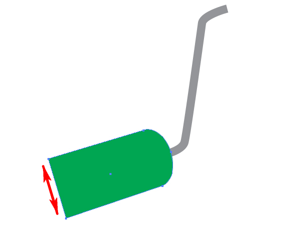
Then take the Rotate Tool (R) and tilt the path in order to join it with the lower end of the gray handle. After that you can take the Direct Selection Tool (A) and change the form of this path slightly to make the left end of it wider. See the following image.
Step 3
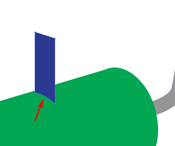
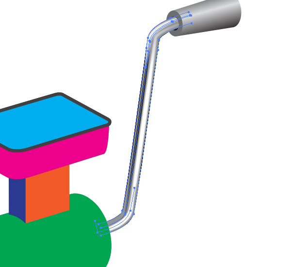
Now illustrate the left wall of the meat receiver by using the Pen Tool (P). Keep in mind that the lower line of this part of the machine must be curved because it intersects the green (round) part of the mincing machine.
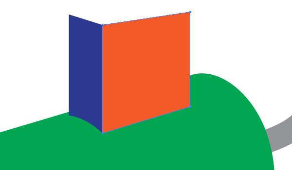
Illustrate a front wall in the same way. The lower line here is straight.
Step 4
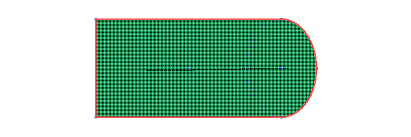
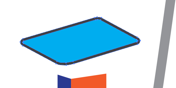
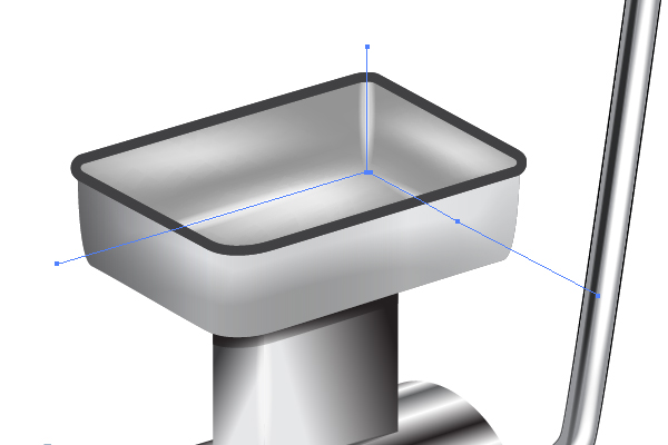
To illustrate the meat receiver, first draw the guide lines (shown with red in the diagram below) using the Line Segment Tool (Back Slash) and lock them in the Layers palette.
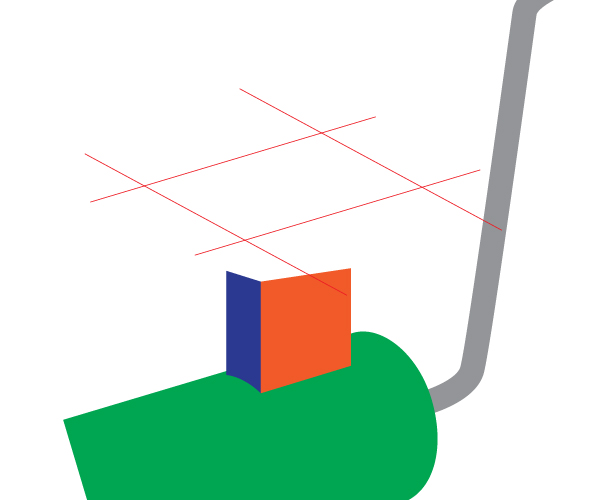
Then draw the shown path with rounded angles basing the directions on the red guide lines.
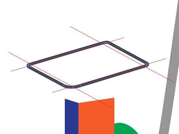
After that go to Object > Expand, Object > Ungroup.
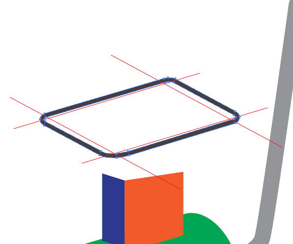
Delete or make the red guide lines invisible. Copy the received compound path and Paste it in Back (Command + C then Command + B). Apply Object > Compound Path > Release.
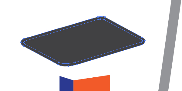
Delete the outer path and change the filling color of the inner path, you should have two paths of the meat receiver after that. Both are shown in the image below.
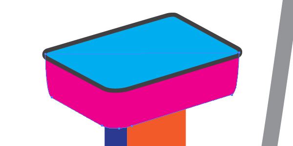
Draw the lateral surface of the capacity. Use the image below as a reference.
Step 5
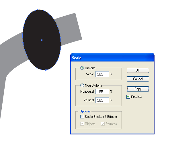
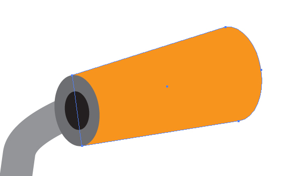
Draw a black ellipse at the right end of the handle.

Go to Object > Transform > Scale, decrease the corresponding values in the dialog box and click the Copy button.
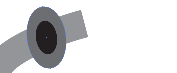
Send the copy of the ellipse backward and change the color of it as shown below.
And illustrate the orange handle as you can see it.
Step 6
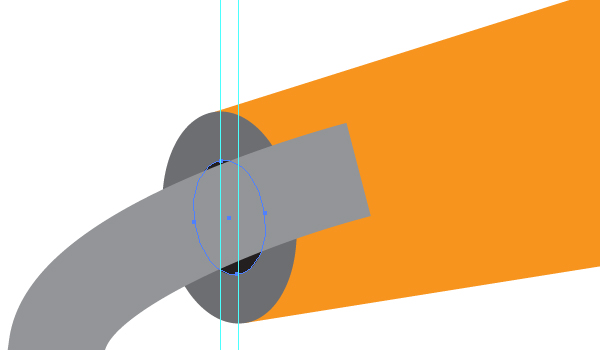
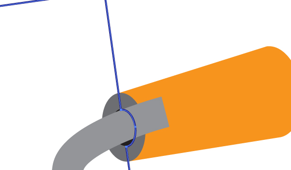
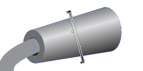
Do you know how to insert the gray detail into the handle? First of all send the handle backward (Command + Left Square Bracket).
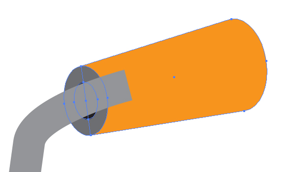
Then zoom into the image and with the small ellipse selected drag the guide line from the left ruler of your artwork and drop it over the top anchor point of the small ellipse. Lock the guide line in the Layers palette.
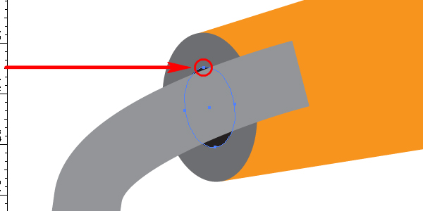
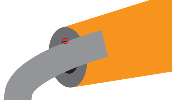
Do the same with the lowest anchor point of the ellipse.
Take the Pen Tool (P) and join these points with each other.
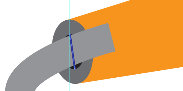
Continue to use the Pen Tool (P) in order to go around the gray detail of the handle.
Then delete the guide lines, and Copy the small ellipse and Paste it in Front (Command + C then Command + F).
Select both paths: the copy of the ellipse and the surrounding blue path and unite them as you did it before. Send the received path forward (Command + Right Square Bracket).
Then select the received path and the gray path of the handle and go to Object > Clipping Mask > Make (Command + 7). The gray detail will be inserted into the orange handle.
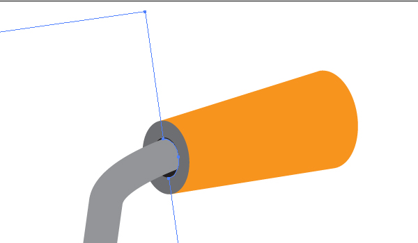
What do you think about Illustrator after this step? I think that it resembles a construction game – Meccano perhaps?:)
Step 7
Illustrate the details of the mincing machine shown below without assistance.
Step 8
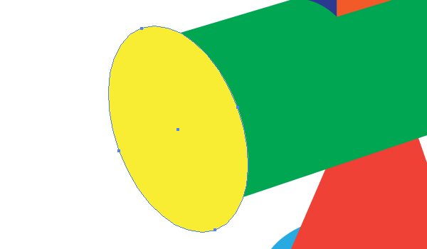
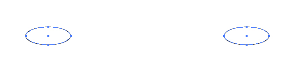
Take the Ellipse Tool (L) and draw a usual elliptical path shown below.

Copy it and Paste in Front (Command + C then Command + F). Move the copy to the right.
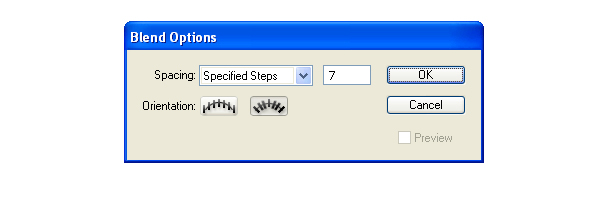
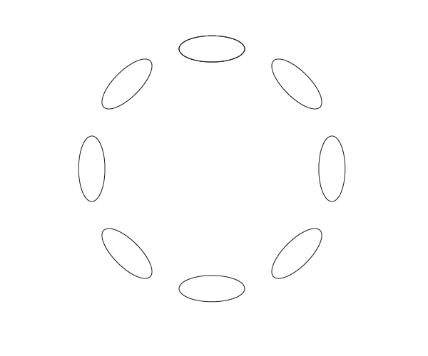
Go to Object > Blend > Blend Options and set the Spacing to Specified Steps, the quantity of steps to 7, and the orientation to Align to Path.
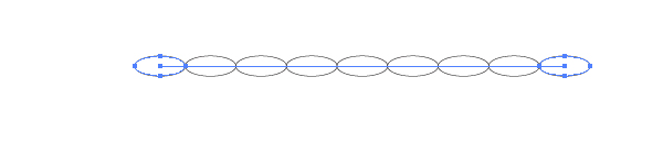
Select both ellipses and go to Object > Blend > Make (Command + Option + B).
Illustrate the usual circle. You can then set the Stroke of the circle and the filling color of it to None.
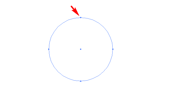
Take the Scissors Tool (C) and click in the top anchor point of the circle. After that select this circle and drag and drop it in the Blend group of the Layers palette.
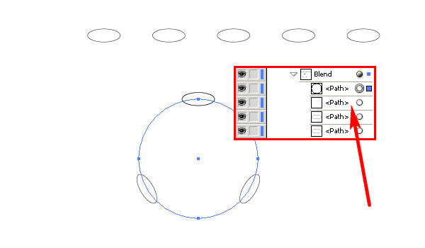
And delete the second (straight) path in the Blend group (shown with an arrow in the diagram above).
Step 9
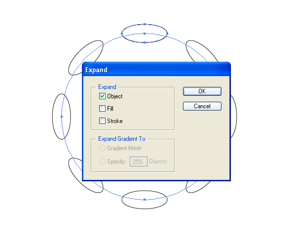
Copy the circle of the blend and Paste it in Front (Command + C then Command + F). Drag and drop it from the blend group. Select the blend and go to Object > Expand.
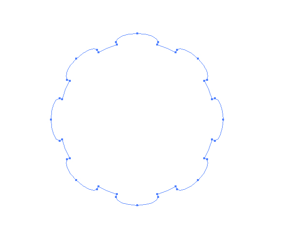
Then unite all the paths of the blend. You should receive the following shape.
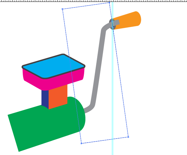
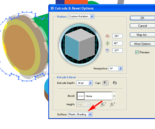
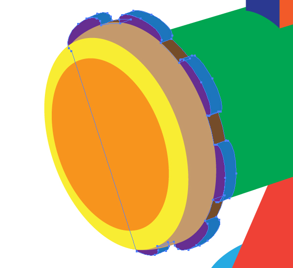
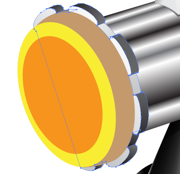
Decrease the opacity of the path, go to Effect > 3D > Extrude & Bevel. Specify the corresponding values in the dialog box in order to locate the received 3D object over the mincing machine accurately. See the image below for reference.
Step 10
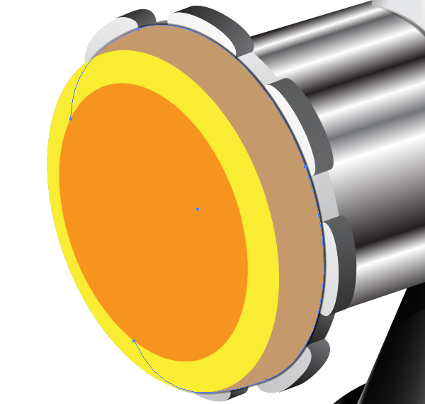
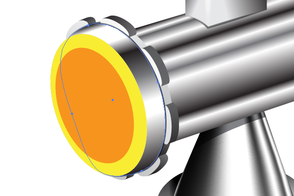
After that change the opacity of the 3D object to 100% again, and click the "3D Extrude & Bevel" link in the Appearance palette in order to change the rendering style of this object (shown with an arrow in the diagram above) to No shading. You should do this in order to decrease the quantity of paths after expanding. Then go to Object > Expand Appearance, and delete the unnecessary paths, and unite all the necessary ones. Paint the received parts of this detail. The main geometry sketch will now be completed. See the helpful image below.
Step 11
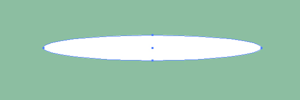
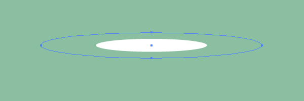
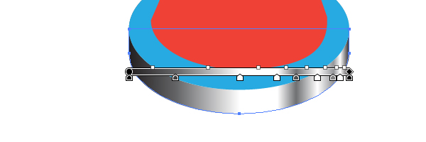
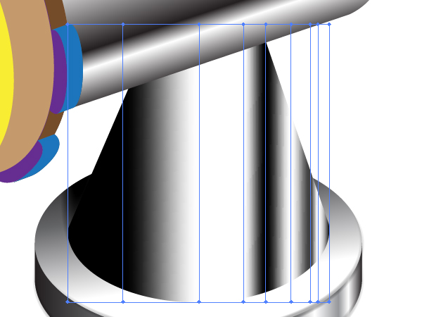
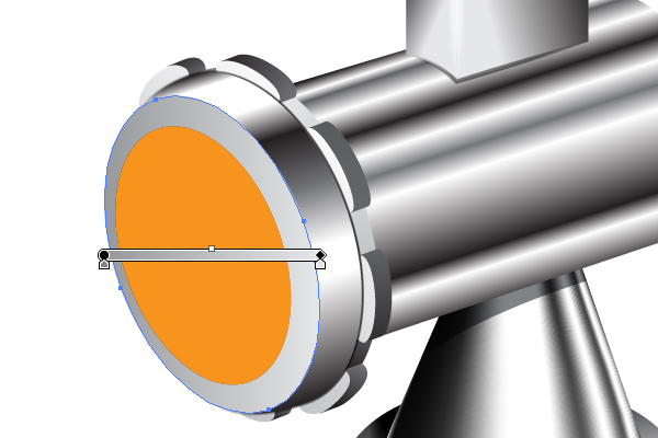
We will now move onto the metallic effects. Take the Ellipse Tool (L) and draw an elongated, horizontal, elliptical path filled with white. See the helpful image below.
Go to Object > Transform > Scale, and set the values shown in the diagram below. Then click the Copy button.
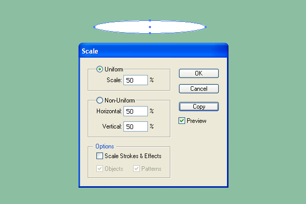
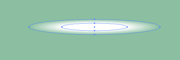
Change the Opacity of the biggest ellipse to 0.
Go to Object > Blend > Blend Options. Set the Spacing to Specified Steps, and the quantity of steps to about 75.

Then go to Object > Blend > Make (Command + Option + B).
Step 12
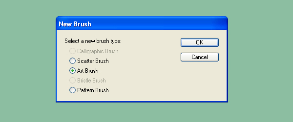
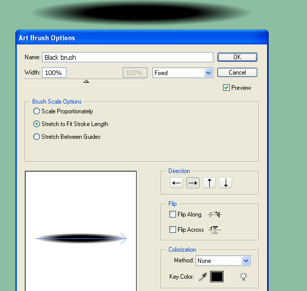
Drag and drop this blend into the Brushes palette. Select the Art Brush option in the dialog box.
Set the items for the brush as shown in the diagram below, and name the brush as "White brush".
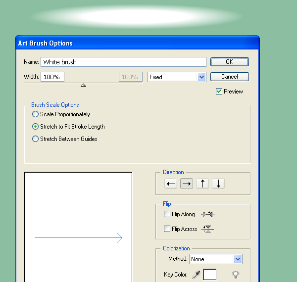
Illustrate the analogous Art brush named as "Black brush".
Step 13
Fill the orange handle with an angled linear gradient.
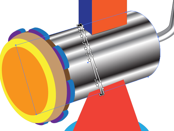
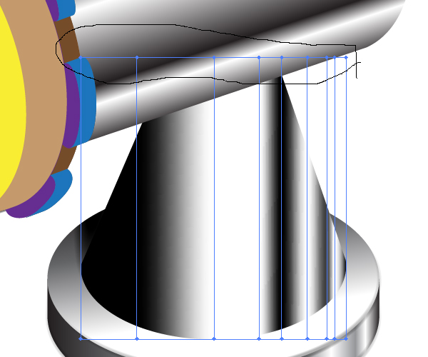
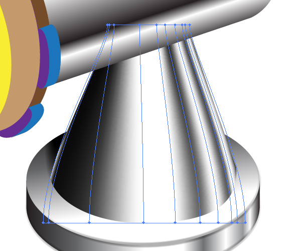
Illustrate the shown path over the gray handle one, and apply the "White brush" to it. Change the opacity of the path and the stroke weight of it if necessary, and then crop the path with a corresponding clipping path as you did it before.
Add other paths to which the Art brushes are applied in order to represent the light distribution over the gray handle detail.
Step 14
The green shape should be filled with an angled linear gradient as shown in the example below.
Fill the lower brown path with a linear gradient.
The blue path should be filled analogously.
Apply the “Black brush” to the following semitransparent paths.
Step 15
Illustrate the next path with the “Black brush” applied to it. You should represent a shadow from the red detail with it. See the image below.
Crop it with a clipping path.
Step 16
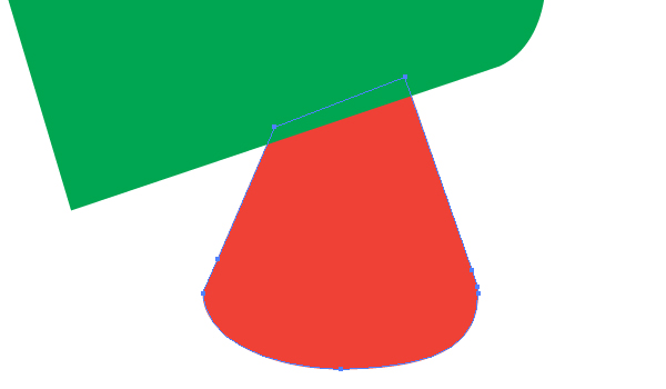
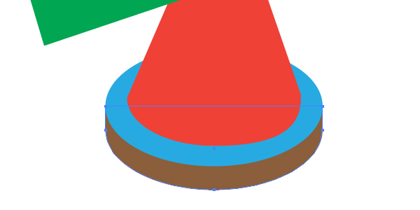
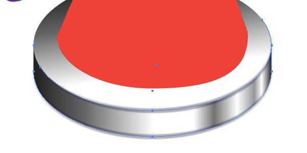
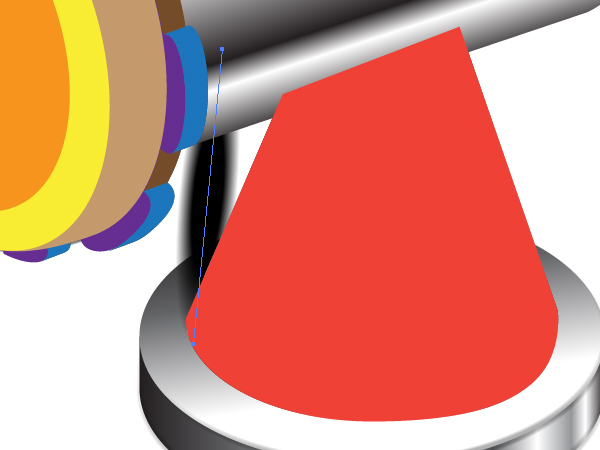
Fill the red path with a linear gradient as shown.
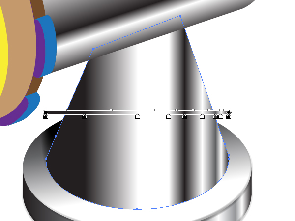
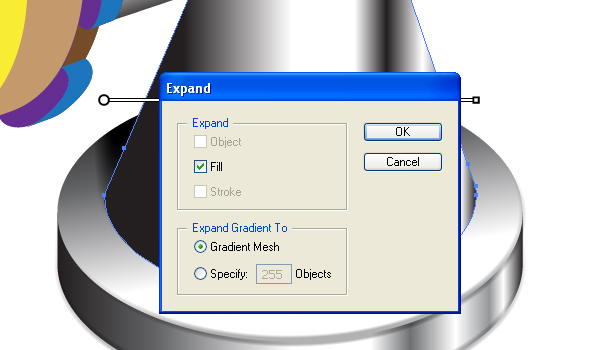
Then while this path is selected go to Object > Expand and expand this gradient as a gradient mesh.
After this manipulation you will receive the following mesh.
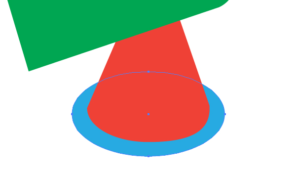
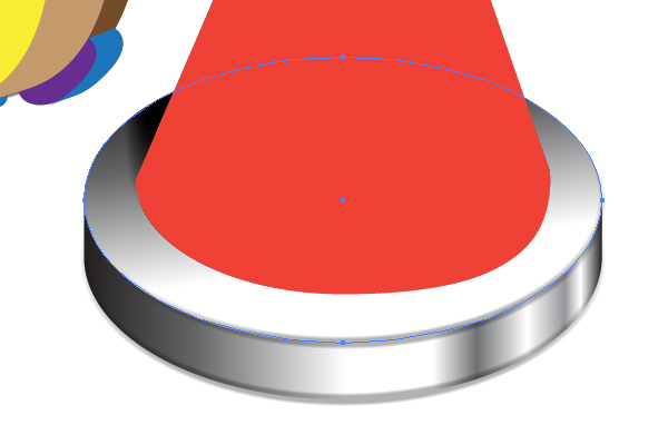
Take the Lasso Tool (Q) and select the top mesh nodes.
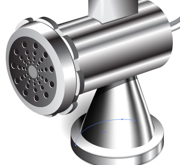
Move then the nodes to each other by going to Object > Transform > Scale. See the helpful image shown below.
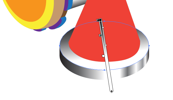
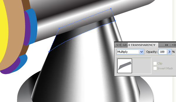
Create a shadow from the top detail on the surface of the conical path. For this sketch a path shown below and fill it with gray.
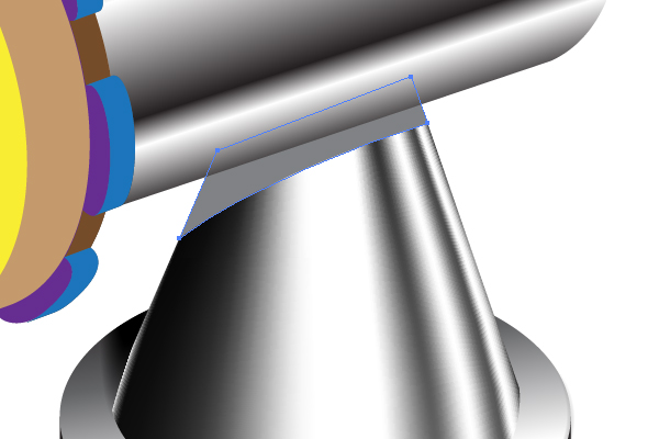
Go to the Transparency palette and set the Blending mode of this path to Multiply.
Step 17
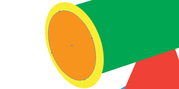
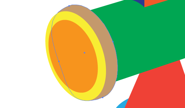
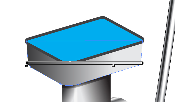
Let’s paint the meat receiver. Fill the shown details of it with angled linear gradients.
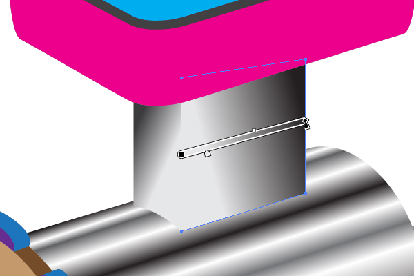
Apply the “White brush” to the following path.
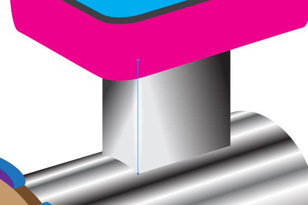
And apply the “Black brush” to the next path.
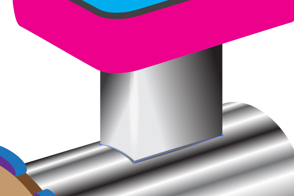
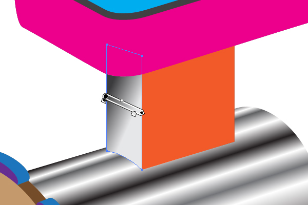
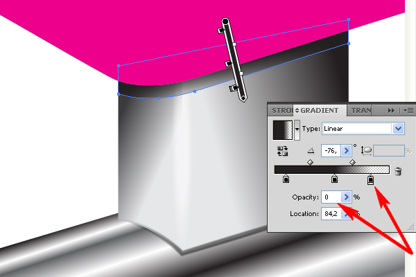
Illustrate the shade from the meat receiver by using an angled linear gradient where the right color-stop has the opacity equal to 0.
Step 18
Fill the crimson detail of the meat receiver with a linear gradient.
Copy it and Paste in Front (Command + C then Command + F). Change the gradient to the opposite one.
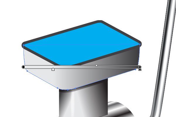
And change the Blending mode of this path to Overlay in the Transparency palette. This action allows you to represent the light distribution more accurately on the composite surface of the meat receiver.
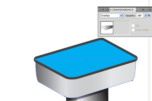
Apply the soft (semitransparent) “Black brush” to the shown path.
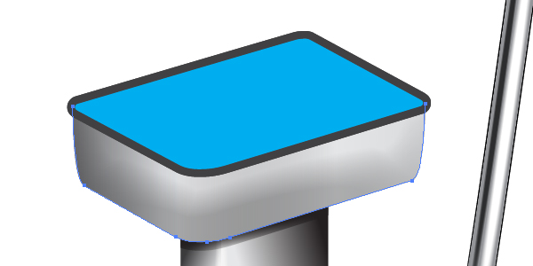
Step 19
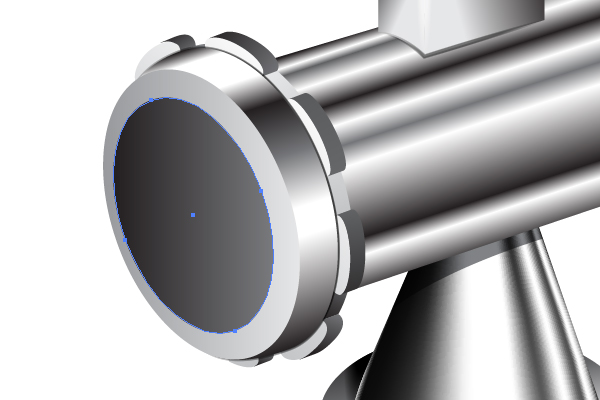
How to paint the inner part of the cavity (blue path)? I advise you to use meshes for this purpose. Let’s try! Select the blue path, and go to Object > Create Gradient Mesh.
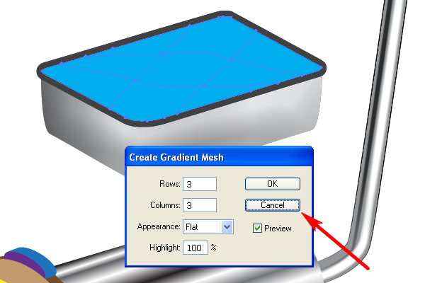
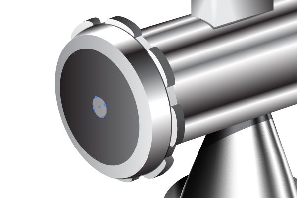
I advise you to click the Cancel button here, because this way of using the meshes is wrong. The automatic locations of mesh lines are not convenient for our task. We will go the other way.
Step 20
Take the Pen Tool (P) and illustrate a quadrangular path beyond the bounds of the blue one. See the image below for reference.
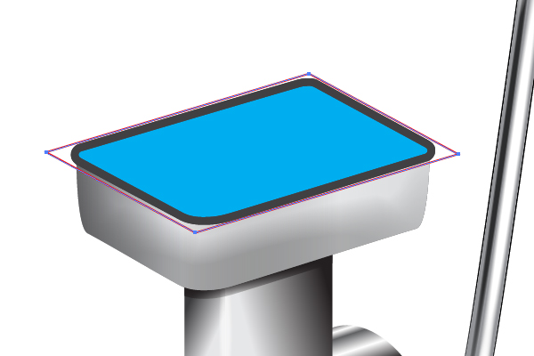
Fill this path with any color and place it under the blue one in the Layers palette.
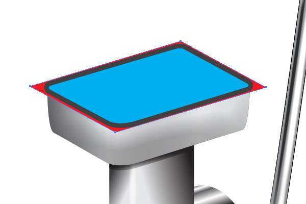
Crop the received red path with a clipping mask created from the blue one.
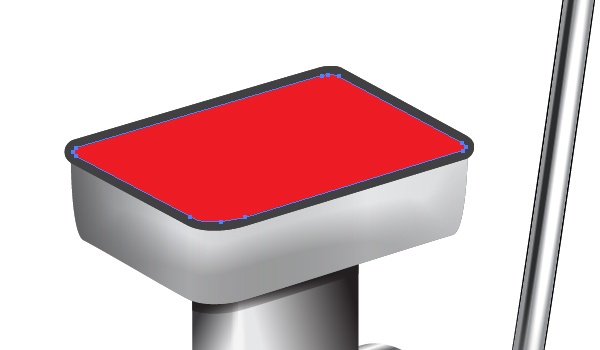
Now lock the Clipping path in the Layers palette, select the red path and go to Object > Create Gradient Mesh.
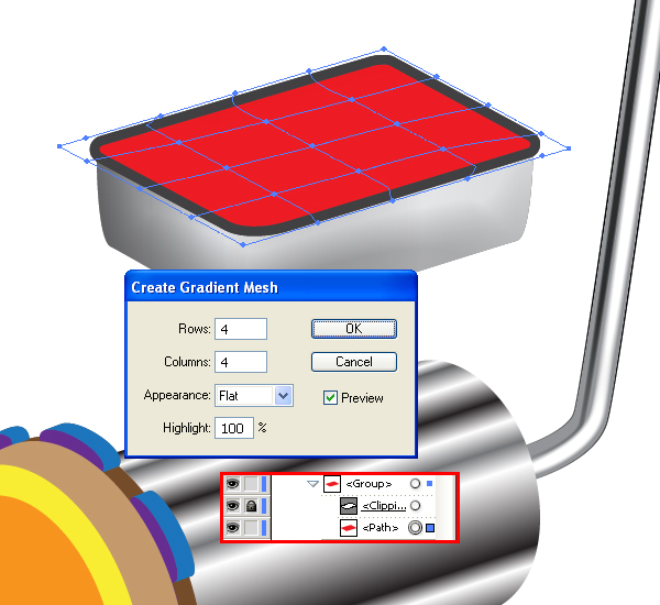
Here you will receive the right distribution of mesh lines. It is more convenient for editing.
Step 21
Change the colors of the mesh nodes.
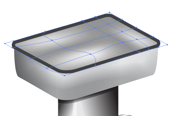
Apply the “White brush” to the following paths in order to represent the right shape of the cavity.
Step 22
The next paths are filled with different angled linear gradients. Up to this point in the tutorial you already know how to achieve this without assistance, so make it yourself. The image below will help you.
Apply the “Black brush” to the following path after that.
The received three paths are filled with angled linear gradients as well. Fill them with gradients as shown.
And illustrate a path in the center of the mincing machine filled with light gray.
Step 23
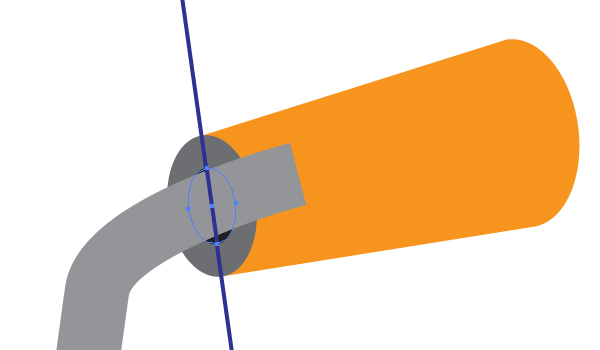
The holes in the mincing machine are made from the expanded blend with the 3D Rotate effect applied.

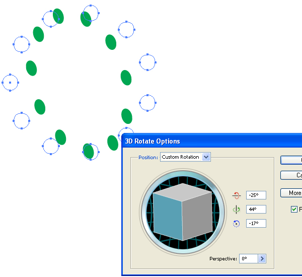
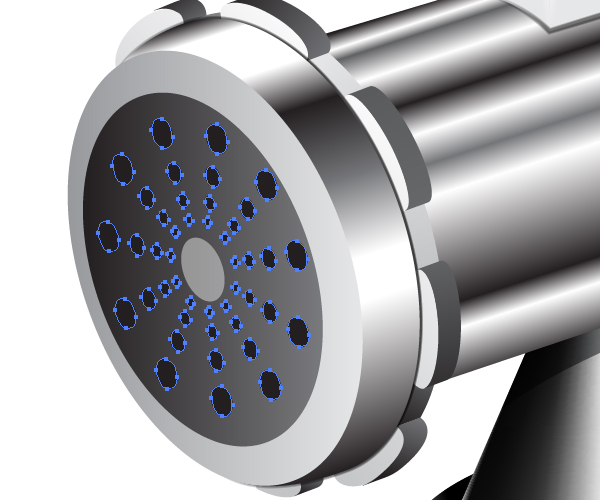
Do this by yourself because you already did it in the Step 8 and Step 9.
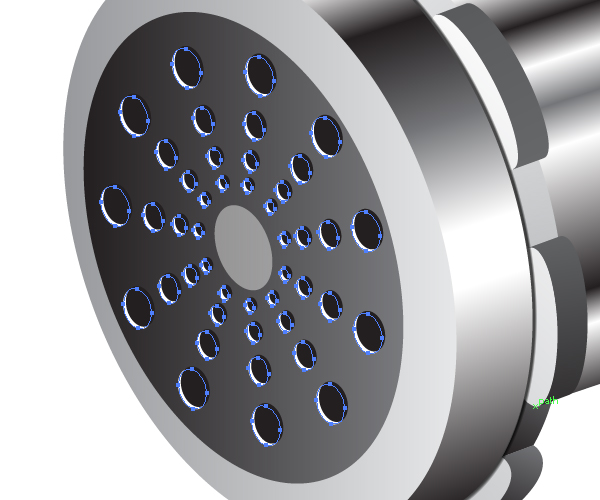
Step 24
Copy the holes and Paste them in Back (Command + C then Command + B). Move it slightly downward and leftward, and fill them with white. Illustrate the shade from the mincing machine using the “Black brush.”
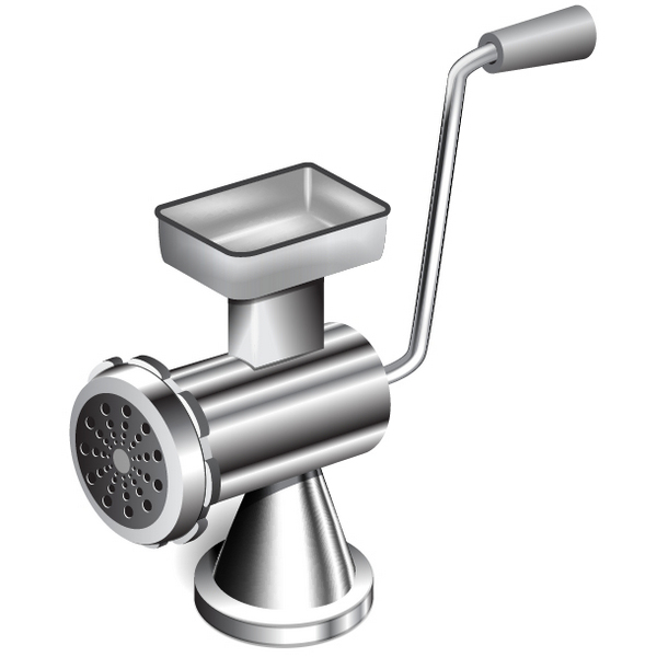
Conclusion
There you have it, a metallic mincing machine. As you can see, the different areas of the object has different lighting depending on how reflective and rounded the shape is. Take a moment to look at the highlights and shadows as this will help you draw almost any kind of shape with a metallic finish.
{excerpt}
Read More