
Marking the Seams
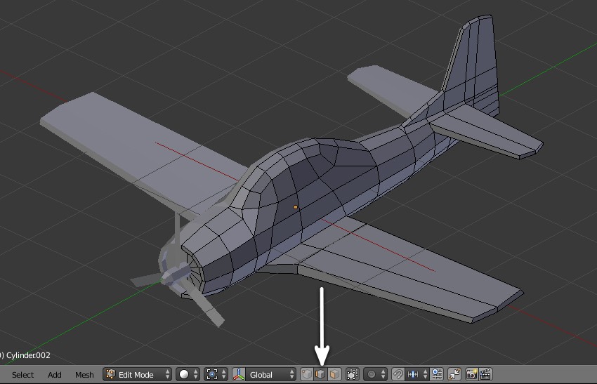
Step 1
Scondary-click on the plane and press Tab to enter edit mode. Click on the Edge
select mode button.
Step 2
Press A on the keyboard to deselect any selected edges.
Hold Shift
and then secondary-click on the edges where the wing starts, one by one, to
select them all.
Press Ctrl-E to bring out the Edges menu
and click on Mark Seams.
You’ll notice that the selected edges turns
red. The seams are from where the mesh will get unstitched onto a flat UV map.

Step 3
Select the bottom edges of the wing as shown in the image. Press Ctrl-E and
click on Mark Seam.

Step 4
Select the edge loop form where the tail wing starts. Hold Shift and then
right click on the edges to select them. Press Ctrl-E and select Mark Seam.

Step 5
Select the bottom edge of the wing from all sides. Hold Shift and then right
click on the edges. Press Ctrl-E and click on Mark Seams.

Step 6
Press A to deselect the edges. Select the front edge loop at the engine. You
can hold Alt and secondary-click on any of the edge to select the edge loop.
Press Ctrl-E and select Mark Seam.

Step 7
Since the model actually half there is no need to mark the center loop as
seam. You can preview the half model by clicking on the eye button to toggle
on/off modifier preview in 3D view port.

Step 8
Press Tab to exit edit mode. Secondary-click on the propeller object to select
it.

Step 9
Press Tab to enter edit mode. Secondary-click on the side edge and mark it seam.
Select the front edge loop (full circle) and mark it as seam. Secondary-click to select and Ctrl-E
to Mark seam.

Press Tab to exit edit mode. Secondary-click on the plane to select it.

UV Mapping the Model
Step 1
Split the 3D viewport by dragging the corner with primary mouse button.

You’ll now have two 3D viewports.

In one of the 3D viewport, click on the Editor type button and select
UV/Image editor. The 3D viewport will change to UV editor.

Step 2
- In 3D viewport, press 3 in the number pad to get into side view.
- With the plane
selected, press Tab to enter edit mode. - Press Ctrl-Tab and select
Face select
mode. - Move the mouse over the main body of the plane and press L. This will select
the main body mesh which is separated by the seams. - Press U on the keyboard to bring
UV
Mapping options. - Select Project From View. This will unwrap the selected mesh as
seen in the , onto the UV Editor.

Step 3
In the UV Editor, hold Alt and then right click on the out edge of the mesh
to select the edge loop.
Press S and then Y to scale it along the Y-axis
to loosen it a bit form the rest of the mesh.
Select the individual vertices on the
tail and move them away so that they don’t over lap on any other vertices or
edge. Do not move the inner vertices or edges. Only spread out the outer edge
loop.

Similarly secondary-click on the vertices on the front part and then press G to
move them away one by one.

Step 4
In the 3D view port, press 7 on the number pad to get into top view.
Select
Face
Select mode.
Move the mouse over the wings top part and press L to select the
mesh separated by the seam. Check from bottom. Nothing else is should be
selected, only the top part of the wings.

Step 5
In top view, with the wings selected, press U to bring out UV Mapping
menu
and select Project from View. The wings are now project on to the UV Editor.

Step 6
Select the outer vertices and edges. Scale and move them away just a little bit so
that they are not getting overlapped by other edges. .

Step 7
In the 3D viewport, press Ctrl-7 to get into bottom view. Move the mouse over
the wings and press L to select them one by one. Press U and select
Project From
View to unwrap them in the UV Editor.

Step 8
In the UV Editor, press A to select all vertices of the wings and press
G to
move them away form the grid. I did this because the UV mesh of all mesh will
land here and would overlap each other. So to avoid this move them from the
default position.

Step 9
In the 3D viewport, press A to deselect any selected face. Move the mouse
over the front part and press L to select it. Press U and select
Project From
View to unwrap the selection onto the UV Editor.

Step 10
Select the outer edge and scale it. Move the selected loop to the side so
that it becomes parallel to the inner loop. Press A to select all vertices and
the G to move it away from the main grid.

Step 11
Press Tab to exit edit mode. Right click on the plane to select it and then
press Tab to enter edit mode. Press A to select all edges. You will see the UVs
in the UV Editor might be jumbled up or overlapping each other.
Arrange all the island groups such that it fits neatly inside the grid. Keep some space for
the propeller UVs. The commands in the UV Editor are same as in 3D viewport:
- Hover over any group and press L to select the group
- Select any vertex or vertices of the group and press Ctrl+L to
select the whole group with connecting vertices. - Hold Shift for multiple select.
- A to deselect / Select all.
- W to bring out the weld/Align menu
- Right click to select any edge / vertices
Here are other editing commands for the UV editor, though they are same as in
3D view.
- G to move
- R to Rotate
- S to scale
- Zoom in/Zoom out – Mouse wheel.
- Pan = Shift-Middle mouse button and drag.
To maximize the UV Editor, move the mouse over the UV Editor and press Ctrl-Up
Arrow. Press Ctrl-Up arrow to toggle back.

Step 12
Press Tab to exit edit mode. Secondary-click on the propeller to select it and
press Tab to enter edit mode.

Step 13
Press A to select all vertices. Press U to bring the UV Mapping menu and
select Unwrap this time. You don’t need it to get projected from view.

Step 14
Move the UVs so that they have some space in between. Select the blade which
is facing the opposite direction and rotate it 180 degrees.
Press R and
then type 180 to rotate
the selection 180 degrees. Adjust the edge loop of the front part as well as shown in the
image.

Step 15
Press A to select all vertices and then press S to scale it down. Press
G to
move them away from the grid.

Step 16
Press Tab to exit edit mode. Secondary-click on the plane to select it. Click on
the modifiers button in the properties window. Press the Apply button in the
Mirror modifier. This will generate the opposite side of the mesh.

Step 17
Hold Shift and secondary-click on the propeller and then the plane. Press
Ctrl-J
to join them.

Step 18
Press Tab to enter edit mode. In the 3D view, press A to select all vertices,
so that UV maps of the whole mesh appear in the UV Editor.

Step 19
Move and adjust the propeller UVs inside the grid.
Press A to deselect the
vertices, move the mouse over any of the UV island and press L to select it and
G to move.
To see more commands and shortcuts, go to step 11.

Step 20
When done, Click on the UVs menu and select Export UV Layout. This will be
the guidelines to paint textures in the painting program.

Select the PNG Format and decrease the Fill Opacity to 0.00.
I kept the default size of 1024×1024 pixels.

Step 21
Now we will bake the Ambient Occlusion data onto the image. This will add
shadow information to a new image, which will be helpful while painting texture
in paint program.
In the UV Editor, press
New button to create a new image onto which you will bake the AO data.

I changed the size to 1024×1024 pixels. Press OK.

A new image is added in the UV Editor.

Step 22
In the 3D view, press A to select all vertices and then press W to bring the
Specials menu. Select Shade smooth. This will give smooth look to the model.

- Press A to deselect the vertices.
- Select only the propeller blades and
center. - Move the mouse over the mesh of the propeller and press L to select each
blade and the center part. - Press 3 in the number pad to get into side view.
- Move the selection away from the plane temporarily so that their shadow does not
appear on the plane, while baking the AO data. - Press Tab to exit edit mode.

Step 23
Click on the World settings button in the properties window. In the Gather
panel, increase the Samples to 15. Higher value will give smooth and noiseless
results.

Step 24
- Click on the Render settings button in the properties window.
- In the Bake
panel, Select Ambient Occlusion in the Bake Mode. - Tick the Normalized checkbox.
- Set Margin to 12 or 16 pixels.

Press the Bake button. After few seconds the image will be updated. In
the 3D View, press Alt-Z to view the model with textured applied. Use Alt-Z
again to toggle back to shaded view.

Step 25
In the UV Editor, click on the Image menu and select Save As Image to save
the image.

In the Save As Image panel, select PNG file format. Choose RGBA to save
transparent image without black background.
Type in the name for the file and
press the Save button.

Texturing and Painting
Step 1
Open the image with Baked AO data, in your favorite image editor. You can use
Gimp or Photoshop.

In a new layer on top, put the UV Layout you exported.

Step 2
Create a new layer in between the Wire and AO layer. This will be the layer
on which you can paint the texture. You can create more layers for painting but
keep them between the Wire and AO Layers.

Step 3
Paint the texture with the wire-frame as guidelines.

Step4
Add another layer and draw the detail lines. Paste the logos/symbols in
their own layer.

Step 5
Set the paint layer to Multiply or hard light or overlay. You will notice the
AO layer will give a nice shadow effect. You can adjust the levels/contrast of
the AO layer to decrease the intensity of shades.
Save the image in .psd format.
Turn off the layer visibility for the UV wire layer and export it to .png or
jpeg format.

Step 6
In 3D viewport (in Blender) and in the edit mode, select all vertices of the
plane by pressing A key. Open your exported PNG image, in the UV Editor.

Step 7
If you don’t see the texture on the model in the 3D view, Press Alt-Z
to enable Texture View Mode.

Step 8
With the plane selected, click on the Materials button in the properties
window and click on the New button to assign a new material.
Rename the
material. In the shading panel, check the Shadeless Tickbox. Since I have baked
the Ambient Occlusion data onto the texture, I can set the material to be
shadeless.
Uncheck it if you want to have dynamic light and shades onto the
object. You can also turn off the AO layer while painting texture in Photoshop
or Gimp and export only the colour map.

Step 9
Click on the Texture button in the properties window. Press the New button.
Rename the texture to whatever you want. In the Image panel, open and
browse for the texture image.
In the Mapping panel, make sure to select
UV for Coordinates.

Creating Variations
Step 1
Turn off the visibility of the painted layer. Add another layer and create
paint with different colour scheme. Export the image with different name in jpg
or png format.

Step 2
In Blender, ensure you are in object mode. Press Tab to exit edit mode.
Secondary-click on the plane to select it. Press Shift-D to make a duplicate. Move
the mouse and primary-click to confirm.

Step 3
Press Tab to enter edit mode. In the UV Editor, click on the Image menu and
Open the new exported image.

Step 4
With the new duplicated plane selected, press the Materials button in the
properties window. Click on the number against the name of the material to make
it a duplicate for the new model. Rename the material.

Step 5
Click on the texture button in the properties window. Click on the number
button to make a new copy of the texture for this new model.
Rename the texture.
In the Image panel, browse for the new image.

Step 6
The aeroplane set is now ready for the game.
