In this intermediate 2-day tutorial we’ll be looking at how to create this futuristic aircraft model using Cinema4D’s primitives, structure tools, Hyper/SweepNURBS, and the Landscape and Sky Shader objects. We’ll also cover how to create simple but effective materials, how to use the Camera shader from MoGraph 2, and take a look at how Advanced Render post-effects such as Highlights and Glow can be used when compositing in Photoshop.
Part 1 – The Camera Ship
Step 1
We’ll start by creating a Sphere object (Object > Primitive > Sphere) with a Radius of 100m, 10 Segments and the Type set to Hexahedron. With this done, make it editable by pressing C on your keyboard. (This tutorial will only include exact values when absolutely needed, and in all other cases it’s down to what YOU think looks good!)

Step 2
Select these 6 polygons at the back of the sphere object and Extrude (Structure > Extrude or D) them slightly.

Step 3
Select the center 2 polygons of extruded surface and Extrude them again as shown.

Step 4
We now need to move the two newly extruded polygons to form the tail of the ship.

Step 5
Select the upper edge of the tail and move it so that the back of the tail now lies flat.

Step 6
Select these two edges underneath where the tail meets the main body and Stitch and Sew (Structure > Stitch and Sew or M~P) them starting from the upper edge.

Step 7
I then tweaked my model to acheive the overall shape I wanted. Move the points until you get a similar result.

Step 8
Using the Knife tool (Structure > Knife or K) with Mode set to Plane and Plane set to Y-Z, cut the tail vertically two times as shown, splitting it into 3 sections.

Step 9
Select these 6 edges on the top of the model.

Step 10
Move the selected edges back along the X-axis. I’ve also moved some of them up on the Y-axis to slightly flatten out the top of the tail section.

Step 11
Select the lowest edge at the bottom of the tail section and move it forward slightly to add a slope to the back of our model.

Step 12
Select the 2 polygons at the very end of the tail and use Extrude Inner on them (Structure >Extrude Inner). Then slightly scale the selected polygons down on the Z-axis.

Step 13
Optional step: Here I’ve tweaked the overall shape of the ship in order to make it a little more aerodynamic. (You can use HyperNURBS (Objects > NURBS > HyperNURBS) to check this how your alterations will look when smoothed.)

Step 14
Select these 6 polygons on the bottom of the front part of the ship and move them up to slightly flatten out the bottom of the main body section.

Step 15
Create a HyperNURBS object (Objects > NURBS > HyperNURBS) and add the ship object to it. Alternatively, if you already added HyperNURBS in step 13 above, simply ensure that it’s enabled.

Step 16
Select the 2 polygons at the end of the tail. Use Extrude to create the nozzle shape, and then Extrude Inner to flatten out the inside section.

Step 17
Select these polygons on the bottom of the ship.

Step 18
Now use Extrude Inner on the selected polygons, and then move them up slightly into the main body.

Step 19
Using the Iron tool (Structure > Iron or M~G) flatten out the selected polygons.

Step 20
Define the shape further by tweaking points and polygons.

Step 21
Select these inner polygons and Set Selection (Selection > Set Selection). An orange triangle will appear next to the ships layer in the objects list. This represents a single selection set. In the selection set properties, give the set a name (in my case Nozzles), and then click the Phong tag for the current layer. Then create a copy of the ship, we’ll need it later.

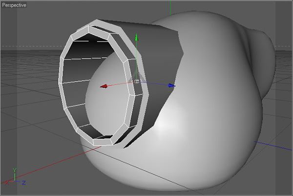
Step 22
Now we’re going to create the lens objects. Start by creating a Tube object (Objects > Primitive > Tube) with an Inner Radius of approx 45m, an Outer Radius of approx 50m, 12 Rotation Segments, a Height of 120-140 and set the Orientation to +X.

Step 23
Duplicate the tube object created above and slighty lower the radius values (here I’ve used 40m and 45m) so that it sits just inside of the larger tube. Then move it forward slightly.
Step 24
Duplicate the tube object again and lower the radius values even further (here I’ve used 38m and 40m) to create another, even thinner tube. Then move it forward slightly so that it matches the image.

Step 25
Create a Disk object (Objects > Primitive > Disk) with an Outer Radius of 38m, and an +X Orientation and place it inside of smallest tube object.

Step 26
Make the disk editable and then select the smallest segment in the center. Move this forward, ensuring to check Soft selection at the Move tool attributes (using a Radius of around 40m and a Linear or Dome Falloff) to make a more lens-like shape.

Step 27
Select all four lens objects (3 tubes and 1 disk) and group them together (Alt+G) under a null object.

Step 28
Add the new null object to the HyperNURBS, to smooth out the lens meshes.

Step 29
We’re now going to add further details to the camera ship, starting with the ribs running around the sides. Make the HyperNURBS object containing the ship body editable and select polygons as shown using Loop Selection (Selection > Loop Selection or U~L).

Step 30
Refine the selection by deselecting polygons inside the ‘nozzle’ area.

Step 31
Extrude the selected polygons with an Offset of around 7m.

Step 32
Now use Extrude Inner on the selected polygons (use Offset lower than 1m).

Step 33
Finally we Extrude the selected polygons back into the body using a negative offset around 6m. With this done, Set Selection (Selection > Set Selection) as before to create a second orange triangle next to your layer name.

Step 34
Here I’ve slightly rotated the main body and moved the lens down into position.

Step 35
Now we’re going to start work on the side nozzles. First create a Cylinder object (Objects > Primitive > Cylinder) with a Radius around 20m and a Height around 130m. Move it into position as shown below :

Step 36
Make the cylinder editable, and then Optimize it (Functions > Optimize, default settings). Select some side polygons as shown.

Step 37
Enable Soft Selection (check Rubber for easier tweaking) and scale the polygons down on the Z-axis.

Step 38
Select the cap polys on both sides of the cylinder and use Extrude Inner on them.

Step 39
Extrude the still selected polygons inwards with a negative offset value. Now create another selection set (and another orange triangle in the tags list) using Set Selection as before.

Step 40
Select the edges running around the outer cap polys at both ends of the cylinder.

Step 41
Use Bevel (M~S) on the selected edges, using a Subdivision of approximately 5 and the Type set to Convex.

Step 42
Tweak the cylinder’s shape to make it more compressed at the back, using the Scale tool with Soft Selection turned on.

Step 43
Now we’ll move onto the lens area details. First create a B-spline object (Objects > Spline > B-Spline) and draw out this arc-like shape.

Step 44
Now create a Circle spline (Objects > Spline > Circle), check the Ring option, change the Radius to 5m, and the Inner radius to 6m. Finally, create a SweepNURBS object and add both the circle and the b-spline objects to it.

Step 45
Duplicate the disk we created earlier from the lens objects, scale it down and place it inside our new tube object. Add it to HyperNURBS to smooth it out.

Step 46
Optional step – placing a camera object for use with the camera shader (only available in Cinema 4D R11.5 with the Mograph 2 module) : Create a Camera object (Objects > Scene > Camera) and place it so that it just sticks out of the lens area, and make sure it’s facing the right way!

Step 47
Now we’ll move onto the materials. First create a new material by double clicking in the Material Manager. In the Material Editor, we want to change the Color to a mid-grey (I’ve used 193 196 199), and change the Brightness to approximately 5%.

Step 48
Turn on the Reflection check-box, change the Brightness to approximately 26%, and check the Additive option.

Step 49
In the Specular options, change the Width to 100%, the Height to approximately 56% and the Falloff to approximately -14%. This will be our base metal material, so name it appropriately.

Step 50
Duplicate the base metal material, and in the Reflection settings, set the Blurriness to about 15% and the Max Samples to 12. This will be the material we apply to all of our details.

Step 51
Create a new material and in the Color settings, apply a Fresnel texture with white to dark grey gradient, and then change the Mix Mode to Multiply.

Step 52
Check Reflection and change Brightness to 20%.

Step 53
At Specular change Height to 150%, Fallof to -20%; this will be lens material.

Step 54
Create a new material. In the Material Editor, change the Color to a light blue (I’ve used 147 204 255).

Step 55
Turn on Luminance and change the Color to a light blue (I used 141 178 255) and the Brightness to 200%. Finally, uncheck Specular and our nozzle material is now ready.

Step 56
Duplicate the nozzle material. In the Luminance settings, change the Color to blue (I used 39 104 255) and the Brightness to 100%. This will be the material we use on our lights.

Step 57
Create another new material, and change the Color to red (in my case 255 42 0).

Step 58
Turn on Luminance, change the Color to red (I used 255 33 0) and the Brightness to 150%.

Step 59
Turn on Reflection, and change the Brightness to approximately 20%.

Step 60
In the Specular settings, change Height to approximately 130% and the Falloff to approximately -25%. Our lens targeting material is complete!

Step 61
Assign the base metal material to the ship body and the side nozzles as per normal.

Step 62
Now we need to recall our Nozzle selection set, so click the first orange triangle in the tags list for the main body layer, and then, in the Set Selection properties, click Restore Selection to select our desired polygons. Assign the nozzle material to the selected polys, and then repeat the process for the center section of the side nozzles object.

Step 63
Using the same process described above, first select the selection set containing the polys inside the ribs, and then assign the lights materials to your selection.

Step 64
Assign the details metal material to all of the objects in the lens area (including the SweepNURBS), except for both of the disk objects.

Step 65
Finally assign the lens material to the bigger disk, and the lens target material to the smaller disk as shown. With this done we can group ALL of the objects together under a single null object. Our camera ship is complete!

Don’t miss more CG tutorials and guides, published daily – subscribe to Cgtuts+ by RSS.